


To perform the phase-shift migration in the prestack domain, the zero-offset dispersion relation must be replaced by the double-square-root (DSR) equation. An additional Fourier transform over offset is also needed.
Constant velocity prestack migration, with output provided in two-way vertical time, in offset-midpoint coordinates (Yilmaz, 1979) in given by:
| |
(10) |
![]()
| |
(11) |
Equation (10) with the proper values of ph and px
to avoid imaginary values of ![]() (Popovici, 1993) can be used to
do prestack migration. To obtain real values of
(Popovici, 1993) can be used to
do prestack migration. To obtain real values of
![]() that
satisfy the downward continuation ordinary differential
equation
that
satisfy the downward continuation ordinary differential
equation
| |
(12) |
| |
(13) |
The DSR migration can be put in a form to allow for separate
migration of each constant-offset section (Popovici, 1993).
For migration of a separate offset section, ![]() , equation (10)
becomes
, equation (10)
becomes
| |
(14) |
The kh integral can be evaluated using the stationary phase method. As shown in Appendix A, the stationary point for isotropic homogeneous media is obtained by finding the maximum (with respect to ph) of the following equation:
| |
(15) |
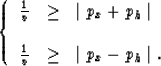
Figure 1 shows T, with ![]() given by equation (17),
as a function of ph for
px=0 (a horizontal reflector) and for px=0.2 (a dipping reflector). To insure that
given by equation (17),
as a function of ph for
px=0 (a horizontal reflector) and for px=0.2 (a dipping reflector). To insure that
![]() remains real, ph in Figure 1 ranges
between 0 and
remains real, ph in Figure 1 ranges
between 0 and ![]() . Clearly, T in Figure 1
is multivalued; The first branch, corresponding to
lower T values, represents the case in which rays from both the source and receiver have angles less
than 90 degrees with the vertical (at the reflection point). The second branch corresponds
to rays from either the source or receiver being overturned at the reflection point. Although the second branch is not applicable to
homogeneous media (rays have always a 90-degree or less
angle with the vertical), it has important implications for
overturned rays in v(z) media. For large offsets and steep reflectors in a v(z) medium, the maximum
of T
(stationary point solution)
usually exists in the second branch (higher T values).
. Clearly, T in Figure 1
is multivalued; The first branch, corresponding to
lower T values, represents the case in which rays from both the source and receiver have angles less
than 90 degrees with the vertical (at the reflection point). The second branch corresponds
to rays from either the source or receiver being overturned at the reflection point. Although the second branch is not applicable to
homogeneous media (rays have always a 90-degree or less
angle with the vertical), it has important implications for
overturned rays in v(z) media. For large offsets and steep reflectors in a v(z) medium, the maximum
of T
(stationary point solution)
usually exists in the second branch (higher T values).
Notice the relatively small curvature that T experiences near its maximum (the solution of the stationary phase problem). The curvature is even smaller for the dipping reflector example. This is a key to obtaining good analytical approximations in solving for ph. The insensitivity of T to ph around the solution implies that even an imperfect ph can result in a good estimate of T. When all is said and done, it is the accuracy of T, which describes the phase shift, that matters the most.
 |

For VTI media, T is slightly more complicated than its isotropic counterpart, and is given by
![\begin{displaymath}
T(p_h) = 0.5 \tau \left[\sqrt{1-\frac{(p_x+p_h)^2 v^2}{1-2 \...
...c{(p_x-p_h)^2 v^2}{1-2 \eta v^2 (p_x-p_h)^2}} \right] + 2 p_h h\end{displaymath}](img54.gif) |
(16) |
 |