


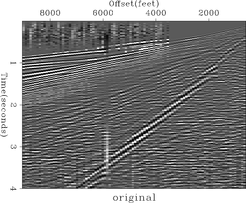
Figure ![[*]](http://sepwww.stanford.edu/latex2html/cross_ref_motif.gif) shows a shot gather with strong coherent
noise at a velocity of about 1800 feet per second.
This noise train is relatively strong and narrow so it is easy to
separate spatially.
For this file, the noise filter was calculated from the data
in a window 0.4 seconds long
with a starting velocity of 1800 feet per second.
This window can be seen from the distribution of the background noise
seen around the ground roll in Figure .
The signal filter was calculated from the data with the previous window zeroed
out, as well as having a start time mute of 3900 feet per second.
shows a shot gather with strong coherent
noise at a velocity of about 1800 feet per second.
This noise train is relatively strong and narrow so it is easy to
separate spatially.
For this file, the noise filter was calculated from the data
in a window 0.4 seconds long
with a starting velocity of 1800 feet per second.
This window can be seen from the distribution of the background noise
seen around the ground roll in Figure .
The signal filter was calculated from the data with the previous window zeroed
out, as well as having a start time mute of 3900 feet per second.
The most expensive part of this process is calculating the
noise filter ![]() , since it is a fairly large filter.
Using a smaller filter reduced the effectiveness of the process,
probably because the noise train is more complicated than it appears.
If the noise is consistent from shot to shot,
the noise filter might be reused to reduce the cost.
Calculating an effective noise filter is likely to be a problem on
many land lines, since the noise will vary from shot to shot, and
since the coupling of the receivers to the ground is variable.
This variability of the coupling will show up as unpredictable
parts of the ground roll.
Since the ground roll is very strong when compared to the signal,
the unpredictable part of the ground roll is likely to have significant energy.
One method of correcting for the variable coupling was presented by
Berlioux and Lumley1994.
If the variations in the coupling are not corrected for,
the results of this process are likely to be unsatisfactory.
The shot file shown in Figure appears to have
an unusually uniform receiver coupling.
, since it is a fairly large filter.
Using a smaller filter reduced the effectiveness of the process,
probably because the noise train is more complicated than it appears.
If the noise is consistent from shot to shot,
the noise filter might be reused to reduce the cost.
Calculating an effective noise filter is likely to be a problem on
many land lines, since the noise will vary from shot to shot, and
since the coupling of the receivers to the ground is variable.
This variability of the coupling will show up as unpredictable
parts of the ground roll.
Since the ground roll is very strong when compared to the signal,
the unpredictable part of the ground roll is likely to have significant energy.
One method of correcting for the variable coupling was presented by
Berlioux and Lumley1994.
If the variations in the coupling are not corrected for,
the results of this process are likely to be unsatisfactory.
The shot file shown in Figure appears to have
an unusually uniform receiver coupling.
 |


Once the signal and noise filters were calculated,
system () was inverted for the noise and the missing data.
As mentioned above,
the noise was initialized with the noise window filtered by the
signal annihilation filter.
If the inversion was attempted with the noise initialized to
zero,
many iterations were required to get a reasonable result.
Even with many iterations, the result was not as good as using a few iterations
with the noise initialized with a good estimate.
For the results shown here, only ten iterations were used.
Little improvement was found when using more iterations.
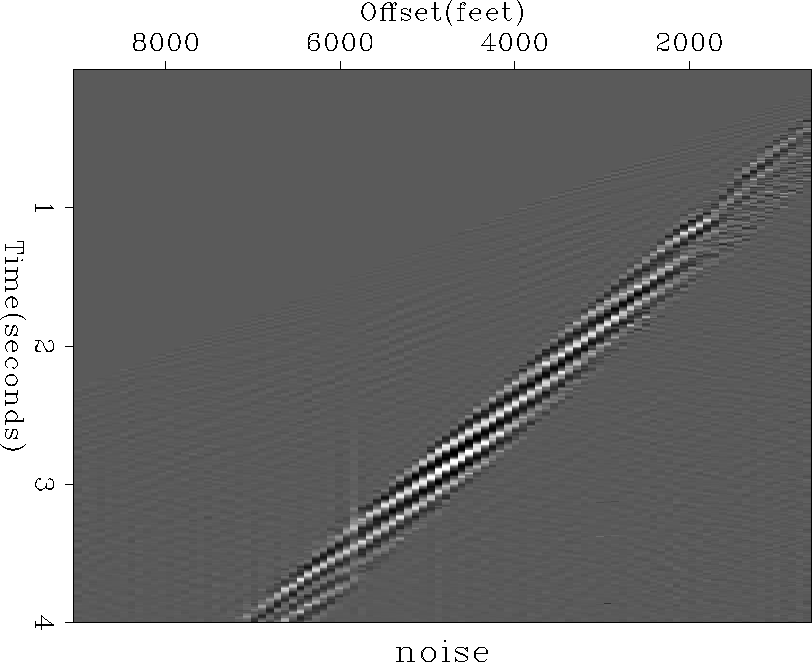
Figure shows the noise estimated by the inversion.
Notice that there is little energy outside the zone where the
noise dominated. There is no obvious signal showing in the noise
section.
When the noise in Figure is subtracted from the
original data in Figure , the resulting signal
is seen in Figure .
Almost all of the coherent noise was removed.
 |
)
using the data from the previous figure.
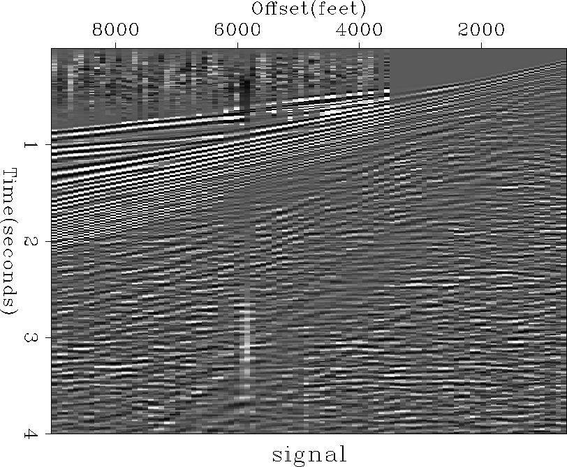 |
There is a small change in the
data character of Figure between
the zone where the noise originally
dominated and the area outside the zone.
This was the result of the treatment of noise not predicted by
either the signal filter ![]() or the noise filter
or the noise filter ![]() ,especially random noise.
The distribution of unpredicted noise is controlled by
the weighting functions
,especially random noise.
The distribution of unpredicted noise is controlled by
the weighting functions ![]() and
and ![]() , as shown in chapter .
Since the value of
, as shown in chapter .
Since the value of ![]() was small in the noise zone,
most of the unpredictable noise fell there.
Outside the noise zone, the value of
was small in the noise zone,
most of the unpredictable noise fell there.
Outside the noise zone, the value of ![]() was large,
keeping the unpredictable noise out of the noise section
and putting it into the signal section.
If this change of character affects analysis of the data,
removing random noise from the entire file
using the techniques of chapter
will eliminate the effect.
was large,
keeping the unpredictable noise out of the noise section
and putting it into the signal section.
If this change of character affects analysis of the data,
removing random noise from the entire file
using the techniques of chapter
will eliminate the effect.
The values of the weighting functions ![]() and
and ![]() will also control
the distribution of events that are predictable with both
will also control
the distribution of events that are predictable with both ![]() and
and ![]() ,as shown in chapter .
If an event is equally predictable with either
,as shown in chapter .
If an event is equally predictable with either ![]() or
or ![]() ,the event will fall into the noise zone because of the small values
of
,the event will fall into the noise zone because of the small values
of ![]() there,
while outside the noise zone, equally predictable events will tend
to fall into the signal.
Generally, events are unlikely to be well predicted by both
there,
while outside the noise zone, equally predictable events will tend
to fall into the signal.
Generally, events are unlikely to be well predicted by both ![]() and
and ![]() because of the different shapes of the filters.
because of the different shapes of the filters.
The results of the inversion were relatively insensitive to
the exact values used in ![]() and
and ![]() . As long as the values outside
the noise zone were between 8 and 40 times the values inside the
noise zone, the results appeared basically the same.
This insensitivity simplifies the calculation of
. As long as the values outside
the noise zone were between 8 and 40 times the values inside the
noise zone, the results appeared basically the same.
This insensitivity simplifies the calculation of ![]() and
and ![]() considerably,
since the signal can be corrected for spherical spreading before the process,
while the noise, even though it will not have its amplitude
perfectly represented in
considerably,
since the signal can be corrected for spherical spreading before the process,
while the noise, even though it will not have its amplitude
perfectly represented in ![]() , can be removed effectively.
, can be removed effectively.
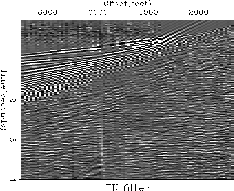
As a comparison,
an F-K filter was run on the previous data, muting out the
noise in the F-K domain.
The results, as shown in Figure ,
appear similar to the inversion results, although some of the ground roll is
left in the shallow section in the F-K plot.
The inversion result shows more character change than the F-K result
in the area
where the ground roll originally dominated, as discussed above.
The F-K filter shows some artifacts of the mute,
which is expected since the mute will produce a long
impulse response in the time-space domain.
Even when the inversion method uses a long filter,
the response of this filter is removed from the output.
In cases where the noise is aliased over a significant part of its
bandwidth, the inversion may be able to
characterize and remove noise more effectively than
simple F-K muting.
 |