

Next: PRESTACK GAUSSIAN BEAM DEPTH
Up: POSTSTACK GAUSSIAN BEAM DEPTH
Previous: The elements of Gaussian
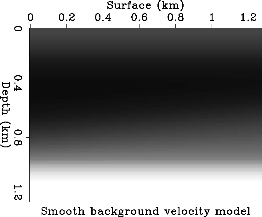
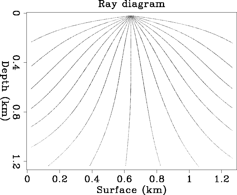
Figure 5 shows a smooth background velocity model. Figure 6 is the ray diagram
of 17 rays traced down from one surface location by the Runge-Kutta method.
The takeoff angles of the 17 rays are equally spaced
from -80 to 80 degrees.
As the rays are traced in constant increments of traveltime, the spatial
distance traversed per step is longer in high velocity zones
(long wavelength zones) than in low velocity zones (short wavelength zones),
as can be seen from the different spacing between dots along rays.
Ray tracing is stopped when the tangent of the ray is close to horizontal.
The ray paths correctly follow the background velocity model.
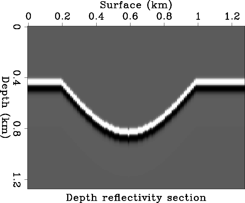
Figure 7 is the reflectivity
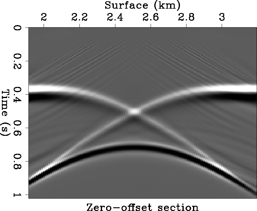
model, with dips ranging from to 45-degree. Figure 8 is the zero-offset
section generated by reverse-time migration (Baysal et al., 1983) running
in the modeling mode. There is some noise around 0.2 second, generated
from the sharp corners of the reflectivity model.
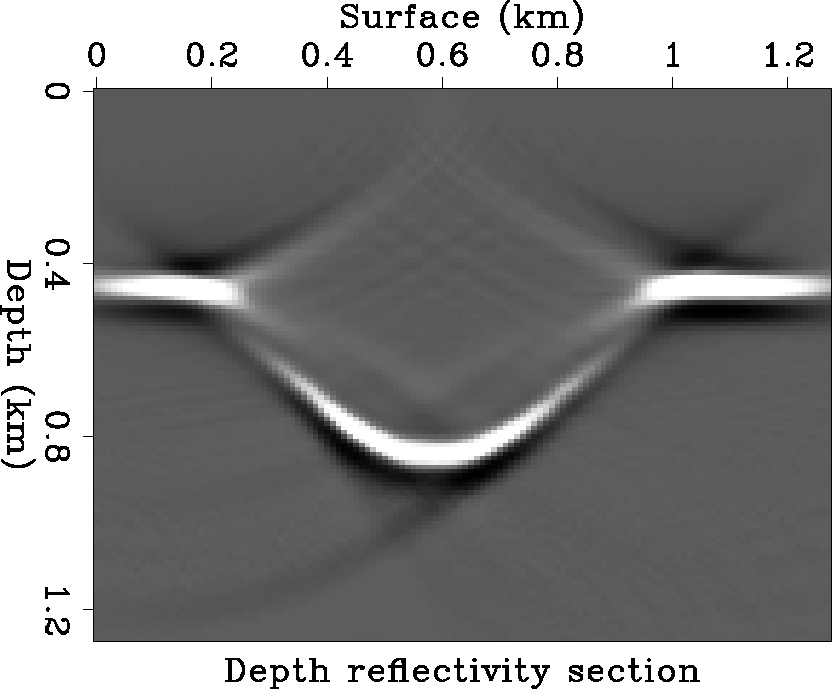
Figure 9 is the reflectivity depth image reconstructed
by Gaussian beam migration based on ray frames. From each surface source
point, 17 rays are traced with takeoff angles equally spaced
from -80 to 80 degrees, as in Figure 6. The reconstructed image
correctly matches the original reflectivity depth model, and the image
background is very clean.
Vel.H
Figure 5 Smooth background velocity
model.


 Ray.H
Ray.H
Figure 6 Ray diagrams of 17 rays traced
from one surface location through the smooth background velocity model
shown in Figure 5.


 Ref.H
Ref.H
Figure 7 Subsurface depth reflectivity
in the smooth background velocity model of Figure 5.


 Section.H
Figure 8 Surface zero-offset
section generated by modeling the subsurface depth reflectivity model
in the smooth background velocity model with the reverse-time migration method
(Baysal et al, 1983).


 ImageGB.H
Figure 9 Subsurface depth
reflectivity image reconstructed by Gaussian beam depth migration.


Next: PRESTACK GAUSSIAN BEAM DEPTH
Up: POSTSTACK GAUSSIAN BEAM DEPTH
Previous: The elements of Gaussian
Stanford Exploration Project
11/17/1997
