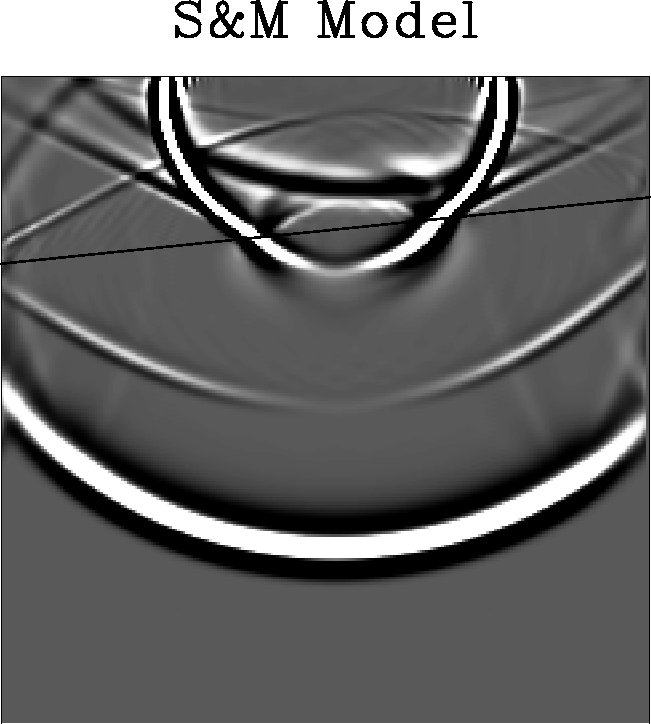
We did this by developing a set of utilities for calculating the elastic properties of equivalent media. The toolkit enables the user to derive the elastic properties of layered and fractured media using S&M theory.
The calculation of equivalent media is based on the parameterisation of
a layer by its thickness, density, and ![]() (compressed subscript
notation) stiffness tensor. The symmetric
(compressed subscript
notation) stiffness tensor. The symmetric ![]() matrix is
rearranged to give three
matrix is
rearranged to give three ![]() submatrices. We call the
submatrices. We call the ![]() form the ``parameter'' form and the three
form the ``parameter'' form and the three ![]() matrix form the
``model'' form. This change is merely a reordering of elements, no
arrithmetic is performed.
matrix form the
``model'' form. This change is merely a reordering of elements, no
arrithmetic is performed.
Layers are combined in a ``group domain'' by simple addition of group
elements. In the group domain the parameterisation takes the form of
two scalars and three ![]() matrices. The mapping from the layer
to group is computed using only
matrices. The mapping from the layer
to group is computed using only ![]() matrix operations as is the
inverse mapping from group to layer.
matrix operations as is the
inverse mapping from group to layer.
The other operation we wish to perform is rotation of the coordinate
frame of the elastic constants of a layer. This is done by expanding
the ![]() stiffness matrix to its full
stiffness matrix to its full ![]() tensor form and then multiplying by a
tensor form and then multiplying by a ![]() transformation
operator.
transformation
operator.
To find the elastic constants for the boundary grid cell, we add the two bounding media in the appropriate ratio, and then rotate the result so the layer dips the right amount.
 |
 |