|
|
|
|
Imaging with multiples using linearized full-wave inversion |
For a towed-streamer geometry, one only needs to introduce (i) the free-surface and (ii) sharp boundaries into the migration velocity
 to begin modeling both primaries and multiples. If the sea-bottom has a sharp interface in
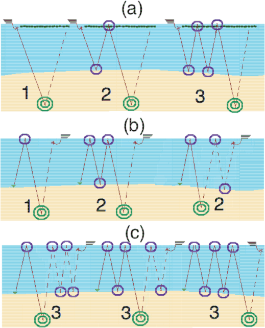
, then equation 2 can model all surface-related multiples as shown in Figure 2 (a). The same is true for ocean-bottom data, which we will discuss next.
to begin modeling both primaries and multiples. If the sea-bottom has a sharp interface in
, then equation 2 can model all surface-related multiples as shown in Figure 2 (a). The same is true for ocean-bottom data, which we will discuss next.
|
|---|
|
DiffOrder3
Figure 2. (a) Ray paths for the primary, the first-order, and the second-order multiples for the towed-streamer acquisition geometry. (b) Ray paths for the down-going mirror and the down-going first-order multiples for ocean-bottom-node acquisition. (c) Ray paths for the down-going second-order multiples for ocean-bottom-node acquisition. Purple-solid circles show scattering off either the free-surface or the background velocity model. Green-double circles show scattering off the reflectivity model. |
|
|
|
|
|
|
Imaging with multiples using linearized full-wave inversion |