|
|
|
|
|
|---|
|
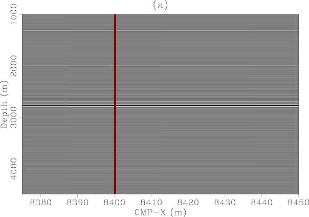
mig3d-inline-const-vel
Figure 28. Migration with constant velocity. Panel (a) is the migrated inline section at CMP-Y=1212.5 m, zero inline subsurface offset and 25 m crossline subsurface offset. Panel (b) is the inline subsurface offset gather taken at CMP-X=8400 m, CMP-Y=1212.5 m and 25 m crossline subsurface offset. Notice again how the multiple is focused as a primary. |
|
|
|
|---|
|
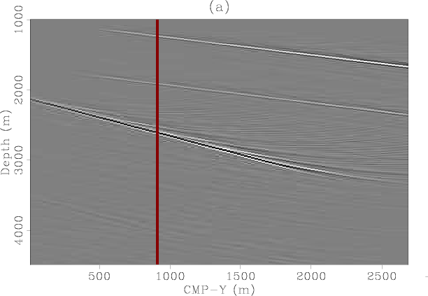
mig3d-xline-const-vel
Figure 29. Migration with constant velocity. Panel (a) is the migrated crossline section at CMP-X=8450 m, zero inline subsurface offset and zero crossline subsurface offset. Panel (b) is the crossline subsurface offset gather taken at CMP-X=8450 m, CMP-Y=912.5 m and zero inline subsurface offset. |
|
|
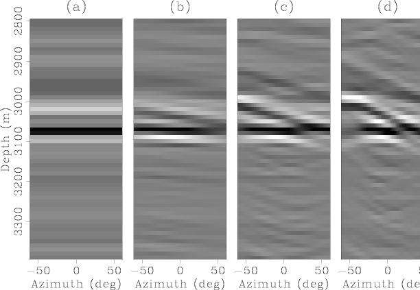
To verify the azimuth dependence of the multiple migrated with the right velocity, I computed new ADCIGs. Figure 30 is equivalent to Figure 20. Although the multiple behaves like a primary in the inline SODCIGs, it behaves different from a primary in ADCIGs as a function of azimuth. Compare Figures 20 and 30. This is also emphasized in Figure 31 which shows the residual moveout of the multiple as a function of aperture angle for fixed azimuth. This figure is the equivalent of Figure 22 for the primary. The effect of the crossline is to force the multiple reflection to take place in two different planes: one from the source to the reflector to the surface and a different one from the surface to the reflector to the receiver. The multiple, therefore, even though it was migrated with the correct velocity, is not equivalent to a primary ADCIGs.
|
|---|
|
az-gath2-const-vel
Figure 30. 3D ADCIG for the water-bottom multiple reflection migrated with water velocity as a function of azimuth. The different panels correspond to different aperture angles: (a) 0, (b) 5, (c) 10, (d) 15 and (e) 20 degrees. Compare with Figures 19 and 20. |
|
|
|
|---|
|
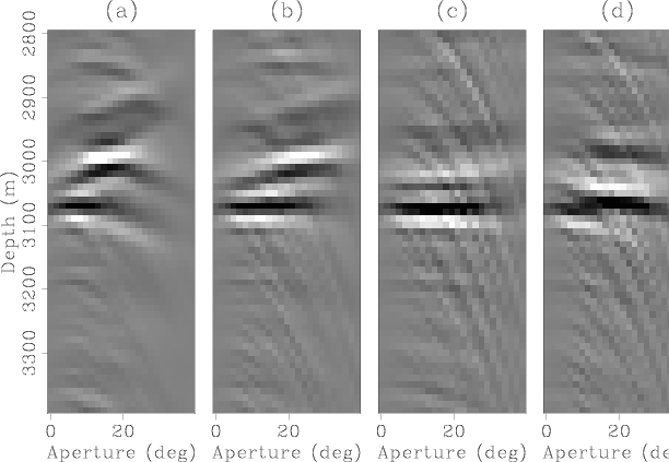
ap-gath2-const-vel
Figure 31. 3D ADCIG for the first-order water-bottom multiple reflection migrated with water velocity as a function of aperture angle. The different panels correspond to different reflection azimuth angles: (a)-40, (b)-20, (c)0, (d)20 and (e)40 degrees. Compare with Figures 21 and 22. |
|
|
|
|
|
|