

Next: Elliptic Coordinate Extrapolation
Up: Shragge and Shan: Prestack
Previous: Introduction
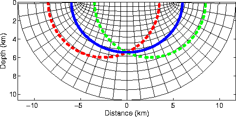
Generating a good coordinate system for RWE prestack migration
requires appropriately linking mesh geometry with the dynamics of
propagating wavefields. Figure ![[*]](http://sepwww.stanford.edu/latex2html/cross_ref_motif.gif) illustrates this for
an idealized shot-profile imaging experiment where source and
receiver wavefields (S and R) are point sources defined at
illustrates this for
an idealized shot-profile imaging experiment where source and
receiver wavefields (S and R) are point sources defined at ![$[{\bf
s},\tau_s=0]$](img2.gif) and
and ![$[{\bf r},\tau_r=\tau]$](img3.gif) in a constant velocity
medium
in a constant velocity
medium  . In this experimental setup, the wavefields
expand outward as spherical wavefronts (dashed lines) described by
|  |
(1) |
An image is generated by applying a correlation imaging condition at
t=0,
| ![\begin{displaymath}
I ({\bf x}) = \sum_{s} \sum_{r} \delta \left[ \tau - \left( ...
...ert + \vert\vert{\bf x}-{\bf s}\vert\vert}{v} \right) \right], \end{displaymath}](img6.gif) |
(2) |
which is the equation of ellipse (solid line). This suggests a
natural link between elliptic coordinate systems and prestack
migration, which is illustrated in Figure ![[*]](http://sepwww.stanford.edu/latex2html/cross_ref_motif.gif) by the
similarity of the drawn isochron and the coordinate mesh.
WhyEC
by the
similarity of the drawn isochron and the coordinate mesh.
WhyEC
Figure 1 Idealized imaging
experiment in a constant medium. Source and receiver wavefields
(dashed lines) are expanding point sources described by fields
 and
and  . The
corresponding image is an elliptic isochron surface
  derived by cross-correlating the source and receiver wavefields
(solid line). Note that the overlain elliptic coordinate system
closely matches (though not identically) the isochron surface
suggesting that this is a good coordinate system for RWE prestack
shot-profile migration.

The keen observer will note that the foci of the elliptic coordinate
system in Figure ![[*]](http://sepwww.stanford.edu/latex2html/cross_ref_motif.gif) were not specified relative to
were not specified relative to
 and
and  . Shifting these points around alters both the
mesh and how well it matches the isochrons. However, this represents two
degrees of freedom that allow us to optimally match mesh geometry to
the wavefield propagation dynamics.


Next: Elliptic Coordinate Extrapolation
Up: Shragge and Shan: Prestack
Previous: Introduction
Stanford Exploration Project
5/6/2007
![[*]](http://sepwww.stanford.edu/latex2html/cross_ref_motif.gif) illustrates this for
an idealized shot-profile imaging experiment where source and
receiver wavefields (S and R) are point sources defined at
illustrates this for
an idealized shot-profile imaging experiment where source and
receiver wavefields (S and R) are point sources defined at ![[*]](http://sepwww.stanford.edu/latex2html/cross_ref_motif.gif) by the
similarity of the drawn isochron and the coordinate mesh.
by the
similarity of the drawn isochron and the coordinate mesh.

![[*]](http://sepwww.stanford.edu/latex2html/cross_ref_motif.gif) were not specified relative to
were not specified relative to
![]() and
and ![]() . Shifting these points around alters both the
mesh and how well it matches the isochrons. However, this represents two
degrees of freedom that allow us to optimally match mesh geometry to
the wavefield propagation dynamics.
. Shifting these points around alters both the
mesh and how well it matches the isochrons. However, this represents two
degrees of freedom that allow us to optimally match mesh geometry to
the wavefield propagation dynamics.