


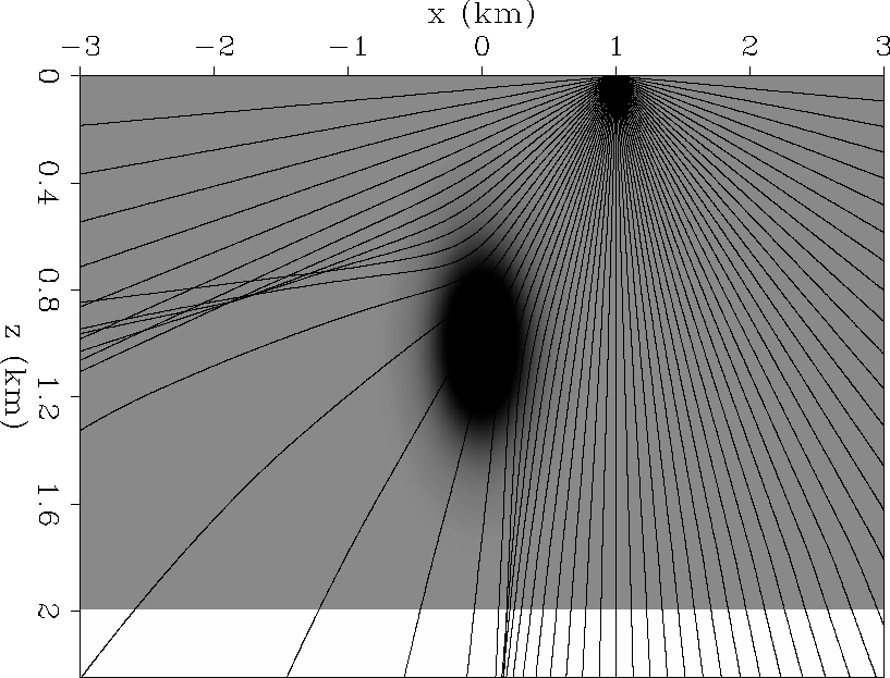
The TRIP synthetic dataset was created from a model with a constant-reflectivity flat reflector lying beneath a Gaussian low velocity anomaly (Figure 1). The data was modeled with the following acquisition geometry: the shots and receivers were positioned every 10 m on the interval ![]() km . We also show rays from the shot position x=1 km, to stress the point that the Gaussian anomaly produces an irregular angle of incidence of waves over the flat reflector (also an irregular sampling of the emergence angles at the surface).
km . We also show rays from the shot position x=1 km, to stress the point that the Gaussian anomaly produces an irregular angle of incidence of waves over the flat reflector (also an irregular sampling of the emergence angles at the surface).
 |


Figures 2 and 3 show the subsurface-offset domain migration and the corresponding angle-domain migration. Notice the different patterns created by the uneven illumination in offset and angle. The subsurface offset is a less intuitive domain than the reflection angle. From Figure 2 it is difficult to interpret at which angles was the reflector illuminated while from Figure 3 it is obvious. At the center of the acquisition the reflector is illuminated from ![]() to
to ![]() . The corner of the reflector is only illuminated at small reflection angles. But in between, due to the low velocity anomaly, there are angles where there is no image.
. The corner of the reflector is only illuminated at small reflection angles. But in between, due to the low velocity anomaly, there are angles where there is no image.
|
mig_off
Figure 2 Shot-profile migration image in the subsurface-offset domain. | 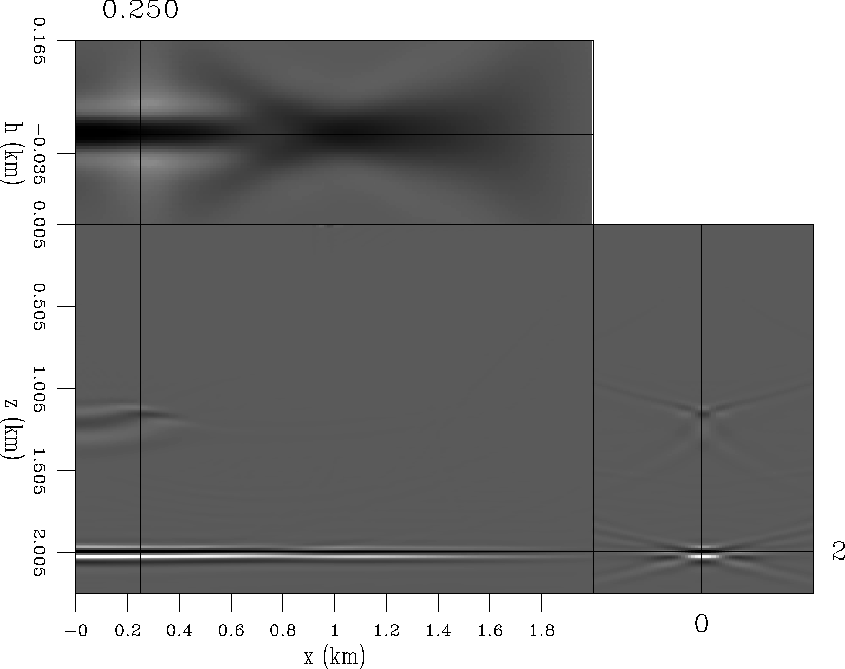 |
|
mig_ang
Figure 3 Shot-profile migration image in the angle domain | 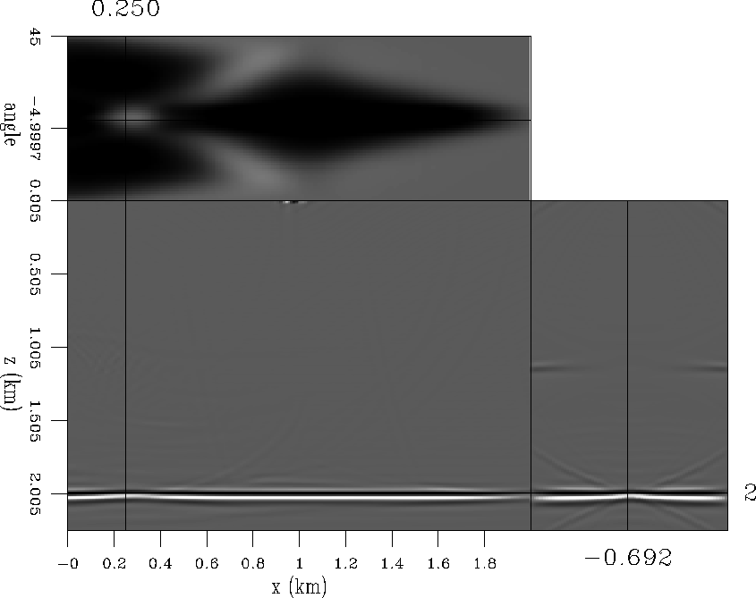 |
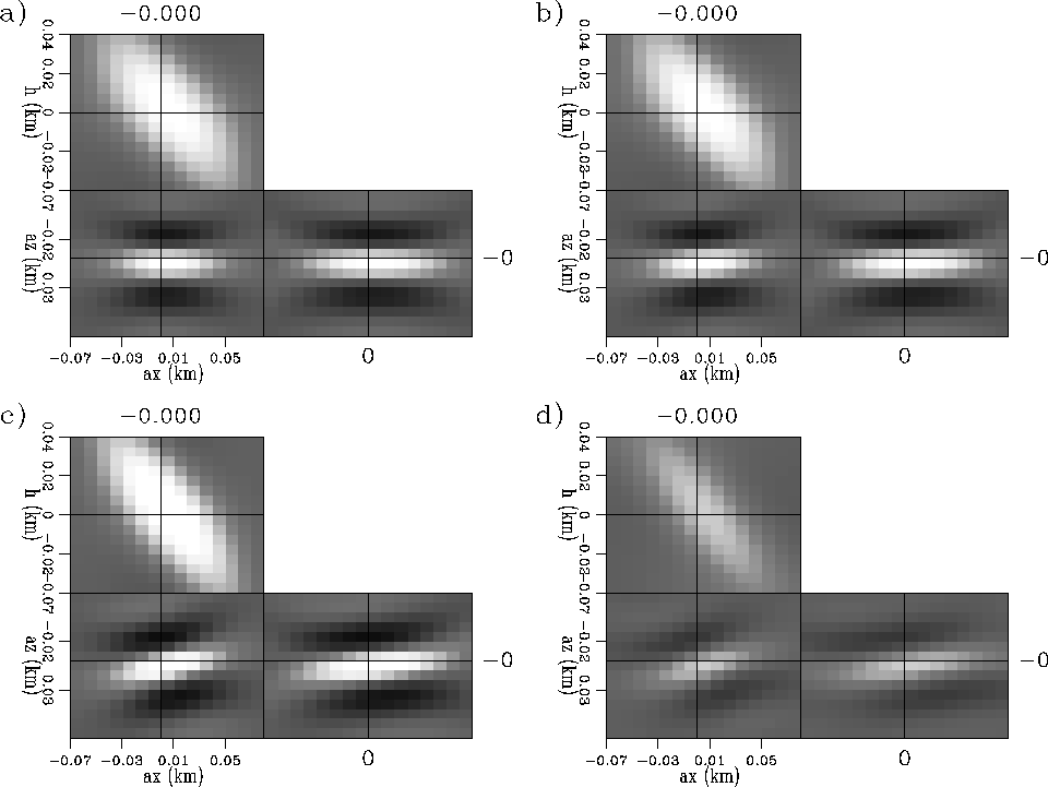
Figures 4 and 5 show the subsurface-offset domain Hessian (![]() coefficients filter). The first (Figure 4) shows the diagonal terms. The second (Figure 5) shows the Hessian off-diagonal terms at four different model space positions.
From Figure 5a to Figure 5d the coordinates go from
coefficients filter). The first (Figure 4) shows the diagonal terms. The second (Figure 5) shows the Hessian off-diagonal terms at four different model space positions.
From Figure 5a to Figure 5d the coordinates go from ![]() , at the center of the acquisition, to
, at the center of the acquisition, to ![]() , at the corner of the acquisition.
, at the corner of the acquisition.
|
illu_off16
Figure 4 Diagonal of the subsurface-offset domain Hessian. | 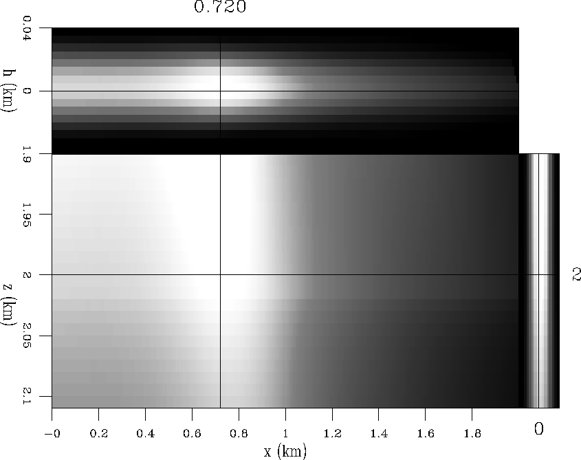 |
 |
![[*]](http://sepwww.stanford.edu/latex2html/movie.gif)
From Figure 4 we could interpret that the reflector has the maximum illumination at x=0.72 km position, but from Figure 5c we can see that the filter shape is tilted (differently than Figure 5a). No more conclusions seems obvious from this Figures rather than there is information hidden in the off-diagonal terms of the subsurface-offset domain Hessian.
Figures 6 and 7 show the angle Hessian (![]() coefficients filter). The first (Figure 6) shows the diagonal terms. The second (Figure 7) shows the Hessian off-diagonal terms at four different model space positions.
From Figure 7a to Figure 7d the coordinates go from
coefficients filter). The first (Figure 6) shows the diagonal terms. The second (Figure 7) shows the Hessian off-diagonal terms at four different model space positions.
From Figure 7a to Figure 7d the coordinates go from ![]() , at the center of the acquisition, to
, at the center of the acquisition, to ![]() , at the corner of the acquisition.
, at the corner of the acquisition.
|
illu_ang16
Figure 6 Diagonal of the angle Hessian. | 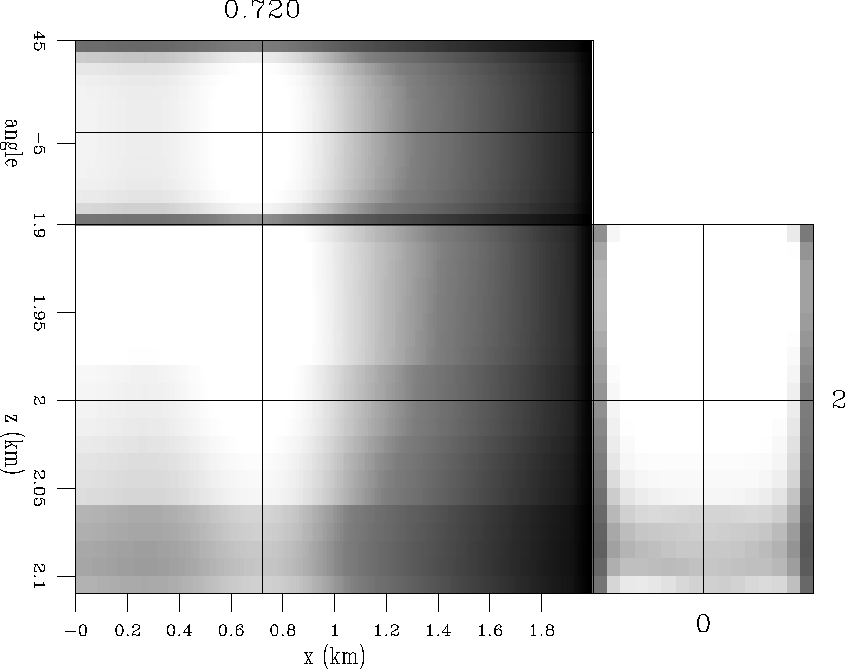 |
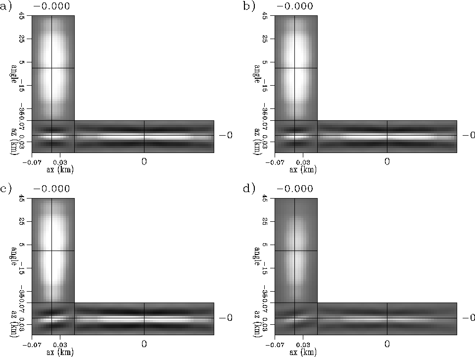 |
The diagonal of the angle Hessian looks similar to the diagonal of the subsurface-offset domain Hessian. But the "filter coefficients" look different. The angle dimension lacks of resolution to be able to interpret which angles get more illumination. The interpretation and improvement of resolution of the angle Hessian are topics of future research.