

Next: Conclusions
Up: Anisotropic residual moveout for
Previous: Conversion of depth errors
To verify the accuracy of the RMO functions derived in this section,
we perform several numerical tests using synthetic data
modeled and migrated using an anisotropic source-receiver modeling
program and its adjoint. As in Biondi (2005b), this
program performed depth extrapolation by numerically solving the
following dispersion relation:
|  |
(37) |
where  is the temporal frequency, and kx and kz are
the horizontal and vertical wavenumbers, respectively.
This dispersion relation
corresponds to the following slowness function Fowler (2003):
|  |
(38) |
where,
|  |
(39) |
is the elliptical component.
We tested the theory with the set of anisotropic Thomsen parameters of
the Taylor Sand ( ) described in Tsvankin (2001).
Figures 8 to
10 show examples of the
application of the RMO function expressed in
equation (30) when perturbing the velocity
uniformly ( ). In the different examples, we didn't
approximate the values of
  but computed them from the values
of
  .
.
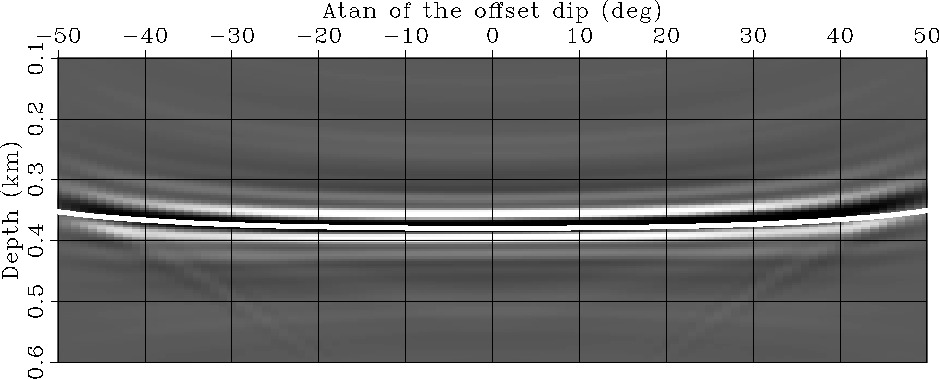
Figure 8 shows that for flat
reflectors, the RMO function we derived accurately tracks the actual
RMO function when the perturbations are sufficiently small to be
within the range of accuracy of the linearization. This is consistent
with the results presented in Biondi (2005b). The
relative lack of accuracy at large aperture angle is due to the
limited offset range we used for the modeling and the migration.
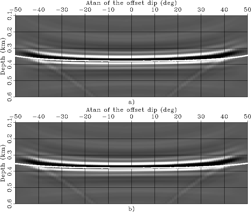
The top panel of Figure 9 shows that for a  dipping reflector the RMO function we derived accurately tracks
the actual RMO function (the relative lack of accuracy at large
aperture angle is due to the limited offset range we used).
However the bottom panel shows that the use of the RMO function given in
Biondi (2005b) (i.e. assuming that the reflector is flat)
gives comparable results.
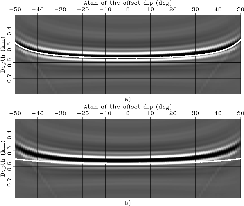
The top panel of Figure 9 shows that
for a  dipping reflector, the RMO function we derived
perfectly matches the actual RMO (we used a larger offset range).
The bottom panel shows that the
RMO function given in Biondi (2005b) (i.e. assuming
that the reflector is flat) gives poor results. It justifies a
posteriori the need for generalizing to dipping reflectors the
concepts of quantitatively relating perturbations in anisotropic
parameters to the corresponding reflector movements in anisotropic ADCIGs.
Rho-95-Alpha-0
Figure 8
ADCIGs obtained for a flat reflector when a constant
anisotropic velocity was perturbed by  . Superimposed onto
the images is the RMO function computed using
the RMO function we derive in this paper (equation (30)).


 Rho-95-Alpha-15
Figure 9
ADCIGs obtained for a  dipping reflector when a constant
anisotropic velocity was perturbed by
  . Superimposed onto
the images are the RMO functions computed: a) using the RMO function
we derived in this paper (equation (30)); b) assuming
that the reflector is flat, i.e. using the equation derived in
Biondi (2005b).


 Rho-95-Alpha-30
Figure 10
ADCIGs obtained for a  dipping reflector when a constant
anisotropic velocity was perturbed by
  . Superimposed onto
the images are the RMO functions computed: a) using the RMO function
we derived in this paper (equation (30)); b) assuming
that the reflector is flat, i.e. using the equation derived in
Biondi (2005b)


Next: Conclusions
Up: Anisotropic residual moveout for
Previous: Conversion of depth errors
Stanford Exploration Project
4/6/2006
 is the temporal frequency, and kx and kz are
the horizontal and vertical wavenumbers, respectively.
This dispersion relation
corresponds to the following slowness function Fowler (2003):
![]() ) described in Tsvankin (2001).
) described in Tsvankin (2001).
![]() ). In the different examples, we didn't
approximate the values of
). In the different examples, we didn't
approximate the values of ![]() but computed them from the values
of
but computed them from the values
of ![]() .
.![]() dipping reflector the RMO function we derived accurately tracks
the actual RMO function (the relative lack of accuracy at large
aperture angle is due to the limited offset range we used).
However the bottom panel shows that the use of the RMO function given in
Biondi (2005b) (i.e. assuming that the reflector is flat)
gives comparable results.
dipping reflector the RMO function we derived accurately tracks
the actual RMO function (the relative lack of accuracy at large
aperture angle is due to the limited offset range we used).
However the bottom panel shows that the use of the RMO function given in
Biondi (2005b) (i.e. assuming that the reflector is flat)
gives comparable results.
 dipping reflector, the RMO function we derived
perfectly matches the actual RMO (we used a larger offset range).
The bottom panel shows that the
RMO function given in Biondi (2005b) (i.e. assuming
that the reflector is flat) gives poor results. It justifies a
posteriori the need for generalizing to dipping reflectors the
concepts of quantitatively relating perturbations in anisotropic
parameters to the corresponding reflector movements in anisotropic ADCIGs.


 dipping reflector when a constant
anisotropic velocity was perturbed by