Shot-profile migration reconstructs the subsurface reflectivity profile by approximately reconstructing the physics of wave-propagation and scattering that generated individual shot records. Central to this formulation is the notion of two independent wavefields: a source wavefield, S, that interacts with discontinuous structure to generate a scattered receiver wavefield, R. The shot-profile migration algorithm consists of two processing steps. The first step is the independent propagation of the S and R wavefields. The second step combines wavefields S and R in a physical imaging condition to generate a map of subsurface reflectivity.
The first shot-profile migration step is an independent extrapolation of S and R, which requires the recursive solution of Claerbout (1985),
 |
(1) | |
The source wavefield extrapolation operator in
Equation (1) includes symbol ![]() to distinguish
between forward- and backscattering migration scenarios. This
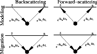
parameter explains the causality arguments illustrated in
Figure
to distinguish
between forward- and backscattering migration scenarios. This
parameter explains the causality arguments illustrated in
Figure ![[*]](http://sepwww.stanford.edu/latex2html/cross_ref_motif.gif) . The four panels represent the
forward (i.e., modeling) and adjoint (i.e., migration) propagation of
wavefields for both the forward- and backscattered scenarios. Causal
propagation is indicated with a forward time-arrow and a positive
sign in the extrapolation operator.
. The four panels represent the
forward (i.e., modeling) and adjoint (i.e., migration) propagation of
wavefields for both the forward- and backscattered scenarios. Causal
propagation is indicated with a forward time-arrow and a positive
sign in the extrapolation operator.
 |
In backscattered modeling (upper left), a surface-excited source wavefield propagates to a point scatterer and then diffracts as a scattered wavefield, R, upward to the surface. Migrating backscattered wavefields (lower left) propagates R backward in time into the subsurface, which requires reversing the direction of the receiver time arrow and the sign of the receiver extrapolation operator. In forward-scattered modeling (upper right), an upgoing source wavefield impinging from below interacts with the point scatterer, again generating an upgoing scattered wavefield, R. Migrating forward-scattered waves (lower right) requires propagating both S and R backward in time into the subsurface, which reverses the direction of the two time arrows and the signs of both extrapolation operators.
The second shot-profile migration step generates an image, I, of
subsurface reflectivity through an evaluation of a physical imaging
condition Claerbout (1971). The most basic imaging condition
extracts the zero-lag coefficient of the correlation of wavefields S
and R. An important extension includes an additional image-space
dimension, subsurface half-offset ![]() , generated by shifting S
and R in opposing directions by distance
, generated by shifting S
and R in opposing directions by distance ![]() prior to correlation
Rickett and Sava (2002). We emphasize that
prior to correlation
Rickett and Sava (2002). We emphasize that ![]() is not equivalent to
the surface offset parameters often encountered in shot-geophone
or Kirchhoff migration approaches. We write this step with the following equation,
is not equivalent to
the surface offset parameters often encountered in shot-geophone
or Kirchhoff migration approaches. We write this step with the following equation,
| |
(2) |