


Next: Aliasing and anti-aliasing
Up: Seismic data preprocessing
Previous: Seismic data preprocessing
The time-distance relation for a shot-receiver pair is
|  |
(9) |
where th is the two-way traveltime of a non-zero-offset shot-receiver pair, hx is the in-line component of the half-offset, and hy is the cross-line component of the half-offset. For simplicity, the connection line of the shot and receiver points is parallel to the x-axis of the Cartesian coordinate system. Therefore, we have the following simple equation which delineates the isochron surface of the prestack migration:
|  |
(10) |
where  ,
, and az are the half-lengths of the axes of the rotary isochron ellipse in the case of constant velocity.
If
and az are the half-lengths of the axes of the rotary isochron ellipse in the case of constant velocity.
If  , then
  ; If
; If  , then
 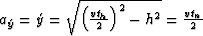 ; If
; If  , then
 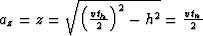 . The variable tn is the two-way traveltime after NMO.
Equation (
. The variable tn is the two-way traveltime after NMO.
Equation (![[*]](http://sepwww.stanford.edu/latex2html/cross_ref_motif.gif) ) can be rewritten as
) can be rewritten as
|  |
(11) |
Further, equation () can be changed into
|  |
(12) |
Defining 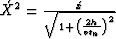 yields:
|  |
(13) |
Equation () is in the form of a poststack migration. Therefore, prestack migration can be explained as a poststack migration on a post-NMO data set.
We know that
|  |
(14) |
Therefore, the dispersion relation of equation () is
| ![\begin{displaymath}
\left(\frac{v}{2} \right) ^{2}\left[k_{\acute{X}}^{2} +k_{\acute{y}}^{2}+k_{z}^{2}\right]=\omega_{n}^{2} .\end{displaymath}](img49.gif) |
(15) |
Substituting () into the above formula yields
| ![\begin{displaymath}
\left(\frac{v}{2} \right) ^{2}\left[k_{\acute{x}}^{2}\left( ...
...{2} \right) +k_{\acute{y}}^{2}+k_{z}^{2}\right]=\omega_{n}^{2},\end{displaymath}](img50.gif) |
(16) |
which can be rewritten as follows:
|  |
(17) |
This is the dispersion relation of the common-offset prestack migration equation.
In the time domain, the dispersion relation is
| ![\begin{displaymath}
k_{\tau}=-sgn\left(\omega_{n}\right) \sqrt{\omega_{n}^{2}-\l...
...\right) t_{n}}\right) ^{2}\right) k_{x}^{2}+k_{y}^{2}\right] }.\end{displaymath}](img52.gif) |
(18) |
Therefore, common-offset prestack time migration (PSTM) can be implemented with the following relation:
|  |
(19) |
The term in the braces represents the wave-field extrapolation, and the integral at tn=0 serves to extract the imaging values.
Then, the common-offset inverse PSTM is
|  |
(20) |
Similarly, the term in the braces represents the wave-field extrapolation, which is an inverse migration. The integral is an inverse Fourier transform.
In the presence of moderate lateral velocity variations, prestack time migration can be expressed as follows:
|  |
|
| (21) |
where  . W1 is the amplitude weight, and
  is the two way traveltime along the imaging ray.
The inverse PSTM is
|  |
|
| (22) |
() give a general theory of data mapping. From here, we will develop some practical approaches for data mapping.
Next: Aliasing and anti-aliasing
Up: Seismic data preprocessing
Previous: Seismic data preprocessing
Stanford Exploration Project
5/3/2005