Our velocity-error estimation method uses ADCIGs computed
after imaging through an offset-to-angle transformation
Sava and Fomel (2003).
Although valid in 2-D,
Biondi et al. (2003) point out that the transformation
assumes the azimuth of the reflectors to be orthogonal to
the azimuth of the acquisition (dip-reflections).
The transformation also ignores the reflection azimuth.
The reflection azimuth is equal to the acquisition azimuth
when the rays do not bend (in constant velocity), or
in case of dip-reflections.
Biondi and Tisserant (2004) extend the method to 3-D.
The transformation maps the migrated inline and cross-line offsets
into the aperture angle (![]() ) and reflection azimuth
angle (
) and reflection azimuth
angle (![]() ).
Hence, after being transformed to the angle domain, each CIG is a
(z,
).
Hence, after being transformed to the angle domain, each CIG is a
(z,![]() ,
,![]() ) cube.
) cube.
|
rays
Figure 2 Source and receiver rays for one event on a 45 dip reflector with a 45 azimuth. |  |
following the characteristics of the fourth reflectors on the model displayed in Figure 1, Figure 2 simulates a reflection from a reflector with a 45 dip and a 45 azimuth in a vertically increasing velocity. It illustrates how different the reflection azimuth can be from the acquisition azimuth in a 3-D configuration. The gray lines symbolize the survey azimuth at constant depth. The black lines symbolize the azimuth between the source and receiver rays at each depth. At the reflection position, the angle between the black and green lines is the reflection azimuth.
 |
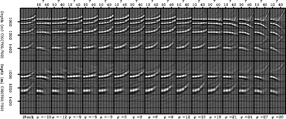
Figure 3 shows slices of the
(z,![]() ,
,![]() ) cube at constant
) cube at constant ![]() for two CIGs
from the model.
The top row is the CIG taken at
x=700m and y=700m, where the steepest reflector is not visible.
The bottom row is the CIG taken at
x=425m and y=425m, where only the two steepest reflectors are visible.
For the remainder of this paper,
we will refer to
these two CIGs as CIG700 and CIG425.
On both rows, the first panel is the stack over the
for two CIGs
from the model.
The top row is the CIG taken at
x=700m and y=700m, where the steepest reflector is not visible.
The bottom row is the CIG taken at
x=425m and y=425m, where only the two steepest reflectors are visible.
For the remainder of this paper,
we will refer to
these two CIGs as CIG700 and CIG425.
On both rows, the first panel is the stack over the ![]() dimension of the cube.
The other panels are slices of the cube at constant
dimension of the cube.
The other panels are slices of the cube at constant ![]() .
As
.
As ![]() increases, the gathers frown downward, then smile
upward, reach a maximum, and frown down again. Note that, although
the velocity is incorrect, the gathers are flat for some
values of
increases, the gathers frown downward, then smile
upward, reach a maximum, and frown down again. Note that, although
the velocity is incorrect, the gathers are flat for some
values of ![]() .Each event is stationary at one particular value of
.Each event is stationary at one particular value of
![]() when the smile is at its maximum.
For CIG700,
when the smile is at its maximum.
For CIG700, ![]() is around
is around ![]() for
for
![]() dip and
dip and ![]() dip reflectors, around
dip reflectors, around ![]() for the
for the ![]() dip reflector, and a bit higher than
dip reflector, and a bit higher than
![]() for the
for the ![]() dip reflector.
For CIG425,
dip reflector.
For CIG425, ![]() is
around
is
around ![]() for
for ![]() dip, and around
dip, and around ![]() for the
for the ![]() dip reflector.
Notice that the values of
dip reflector.
Notice that the values of ![]() from one CIG to
another are comparable for reflectors with the same dip.
Since the gathers are stationary for the
correct
from one CIG to
another are comparable for reflectors with the same dip.
Since the gathers are stationary for the
correct ![]() value, the stack carries some information about the
reflection azimuth.
value, the stack carries some information about the
reflection azimuth.
This analysis can be done whether the migration velocity is correct or not. If the velocity is incorrect, however, the measured values are apparent reflection azimuth angles. The difference between the true reflection azimuth and the apparent one is due to the incorrect ray-bending when the velocity is incorrect.
We next describe how to estimate the velocity error from the ADCIGs with a RMO function.