


Next: About this document ...
Up: REFERENCES
Previous: Downward continuation with the
While we have maintained our coordinate system thus far in parallel
with a shot-receiver migration strategy, we will now detail the
evaluation of the imaging condition with the order of operations
normally associated with shot-profile migration. In fact, the
convolution of the source and receiver grids associated with the
imaging condition (and gives rise to imaging condition aliasing) can
be performed/implied before the migration which is common to resorted
mh-coordinate migrations or at each depth step within the
migration. As we have maintained the distinctiveness of the source
and receiver grids to this point, the convolution of their axes must
now be evaluated.
Calculating Common Image Gather (CIG) offsets involves the evaluation of an imaging
condition at all acceptable values of  and
and  . This gives rise
to two new image space variables: the horizontal image coordinate for
the earth model,
. This gives rise
to two new image space variables: the horizontal image coordinate for
the earth model,
 , and the subsurface horizontal offset coordinate,
  . These
variables have much similarity to the data space variables midpoint
and offset. In a strictly v(z) medium, these axes overlay.
However, in more complicated media, the midpoint variable
is somewhat misleading. This is because the wavefield continuation
extrapolates energy from a midpoint on the surface to a different
midpoint as the wavefields are successively downward-continued. Thus,
mixing these two ideas is inappropriate.
Source and receiver coordinates and horizontal and sub-surface offset
coordinates are related through transforms
. These
variables have much similarity to the data space variables midpoint
and offset. In a strictly v(z) medium, these axes overlay.
However, in more complicated media, the midpoint variable
is somewhat misleading. This is because the wavefield continuation
extrapolates energy from a midpoint on the surface to a different
midpoint as the wavefields are successively downward-continued. Thus,
mixing these two ideas is inappropriate.
Source and receiver coordinates and horizontal and sub-surface offset
coordinates are related through transforms  and
and  .The new coordinate, , a derived parameter with a magnitude
equal to an integer multiple of
.The new coordinate, , a derived parameter with a magnitude
equal to an integer multiple of  , is naturally represented as the
product of an integer multiplication factor h and horizontal image
space discretization interval (i.e.
, is naturally represented as the
product of an integer multiplication factor h and horizontal image
space discretization interval (i.e.  ) that will most
commonly be unity.
) that will most
commonly be unity.
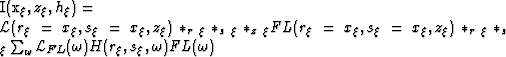
Using these definitions, the image cube may be constructed by applying
the general correlation imaging condition to wavefield W,
| ![\begin{displaymath}
I(x_{\xi},z_{\xi},h_{\xi})=\sum_{\omega}\left[\d(\r-h_{\xi})...
...\xi}\d(s_{\xi}+h_{\xi})\right]\d(\r-x_{\xi})\d(s_{\xi}-x_{\xi})\end{displaymath}](img57.gif) |
(17) |
Note that this expression reduces to the familiar zero subsurface
offset form when  ,
,
|  |
(18) |
The convolution arguments applied to wavefield W, in equation
(18), yield
|  |
|
| (19) |
Before continuing with this development, it is useful here to stop and
interpret the meaning of equations (18) and
(20). The imaging condition itself builds the image-space
coordinate axes x and h during the convolution expressed above.
The arguments within the wavefield W of equation (20)
are the equations of a line. This line, , defines the axis
for surface location of the image, and is independent of any
assumptions about surface midpoints during the experiment. This is
one reason ![[*]](http://sepwww.stanford.edu/latex2html/foot_motif.gif) we have avoided using the midpoint variable, m. These two
coordinates indeed share many traits, though the midpoint concept is an
arbitrary, while intuitive and convenient, coordinate transform. Surface
location, , is a rigorous development required by the imaging process.
we have avoided using the midpoint variable, m. These two
coordinates indeed share many traits, though the midpoint concept is an
arbitrary, while intuitive and convenient, coordinate transform. Surface
location, , is a rigorous development required by the imaging process.
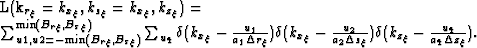
Continuing our derivation, we now reintroduce the lattice in
equation (16) to the imaging condition which yields,
|  |
(20) |
However,  is an integer shift by and is defined
only at known points on the lattice allowing the index of the
Shah function to be shifted to yield,
is an integer shift by and is defined
only at known points on the lattice allowing the index of the
Shah function to be shifted to yield,
|  |
(21) |
Expanding lattice  into its components
  and FL,
and applying a Fourier transform over coordinates , , and  yields,
![\begin{multline}
I(k_{x_{\xi}},k_{z_{\xi}},k_{h_{\xi}})=\left[{\cal L}(k_{r_{\xi...
...mega}{\cal L}_{FL}(\omega) H(\r,s_{\xi},\omega) FL(\omega)\right].\end{multline}](img65.gif)
The Rect functions of coordinates  and
and  are collapsed back to a
single Rect function in
are collapsed back to a
single Rect function in  , where the frequency limit is given by
min
, where the frequency limit is given by
min . The min function arises
because the maximum grid-spacing along either shot or
receiver axis alone dictates the aliasing criteria for the kx-axis.
This also allows for simplified calculations in the particular case.
Generally, however, the bracketed expression in
equation (
. The min function arises
because the maximum grid-spacing along either shot or
receiver axis alone dictates the aliasing criteria for the kx-axis.
This also allows for simplified calculations in the particular case.
Generally, however, the bracketed expression in
equation (![[*]](http://sepwww.stanford.edu/latex2html/cross_ref_motif.gif) ) is
) is
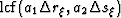
The summations of the delta functions over u1 and u2 collapse to a single
summation over the variable with the lowest common factor (lcf),
|  |
(22) |
The horizontal image coordinate is being sampled at a spacing
 .Thus, for aliasing to be absent the following condition must hold,
|  |
(23) |
where  and
and  are the Nyquist frequencies defined by
fundamental sampling interval
are the Nyquist frequencies defined by
fundamental sampling interval  and
and  .
Thus, the alias-free wavefield is given by the following geometry
.
Thus, the alias-free wavefield is given by the following geometry
| 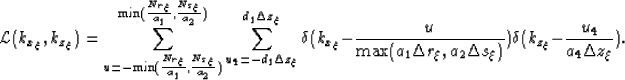 |
(24) |
Notice that for the simplified case of zero-offset migration, the
pre-supposed notion that there are no operator aliasing artifacts
introduced can be shown conclusively within the presentation above.
Without two different sampling intervals, be they source/receiver or
orthogonal surface coordinates, there are no choices for the min
operator in equation () nor the max operator of
equation (25). Instead, the sole variable available,
surface location x, dictates the sampling of the model space.
Notice that for the simplified case of zero-offset migration, the
pre-supposed notion that there are no operator aliasing artifacts
introduced can be shown conclusively within the presentation of the
above results. Without two possibly different sampling intervals, for
source and receiver grids, there are no choices for the  operator in equation (24) nor the
  operator of
equation (25). Instead, the sole variable available,
surface location, dictates the sampling of the model space. This does
not however release zero-offset migrations from the ramifications of
image condition aliasing, as the implied correlation of the source
wavefield associated with source-receiver migrations is still present.
operator of
equation (25). Instead, the sole variable available,
surface location, dictates the sampling of the model space. This does
not however release zero-offset migrations from the ramifications of
image condition aliasing, as the implied correlation of the source
wavefield associated with source-receiver migrations is still present.
Next: About this document ...
Up: REFERENCES
Previous: Downward continuation with the
Stanford Exploration Project
5/23/2004