


Figure 5 shows a depth slice
(z=580 meters)
of the migrated image of the SEG-EAGE salt data set.
The crosshair is centered at a horizontal location
where the top of the salt dips at approximately
50 degrees in the cross-line direction
and is flat along the in-line direction.
Figure 6 shows
the ADCIGs computed at the location marked by the crosshair.
Figure 6a
was computed using the 2-D relationship
[equation (16)],
whereas
Figure 6b
was computed using the 3-D relationship
[equation (17)].
The aperture angle is overestimated in the gather on
the left (apparent maximum aperture is about 60 degrees),
and correctly estimated in the gather on the right
(apparent maximum aperture is about 48 degrees).
This error is consistent with
the factor ![]() that is neglected in
the 2-D case.
Notice that the bottom of the
salt reflection (
that is neglected in
the 2-D case.
Notice that the bottom of the
salt reflection (![]() 2,100 meters) is unchanged,
because it is flat.
2,100 meters) is unchanged,
because it is flat.
|
comp-2d-vs-3d-depth-slice
Figure 5 Depth slice (z=580 meters) of the migrated image of the SEG-EAGE salt data set. The crosshair is centered at a horizontal location where the top of the salt dips at approximately 50 degrees in the cross-line direction. | 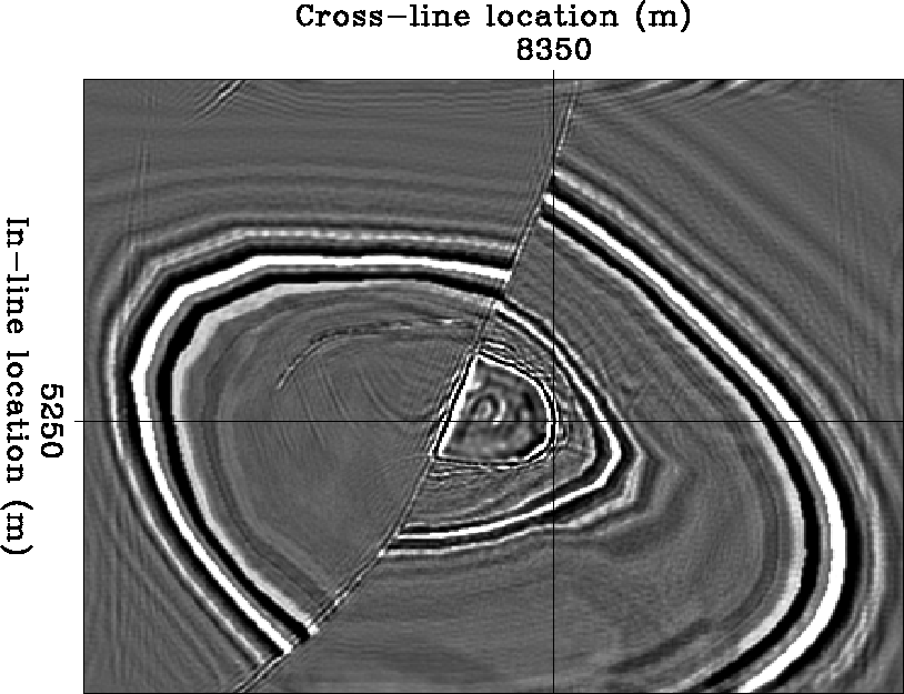 |


|
comp-2d-vs-3d-adcigs
Figure 6 ADCIG computed using the approximate 2-D relationship (panel a), and ADCIG computed using the correct 3-D relationship (panel b). The aperture angle | 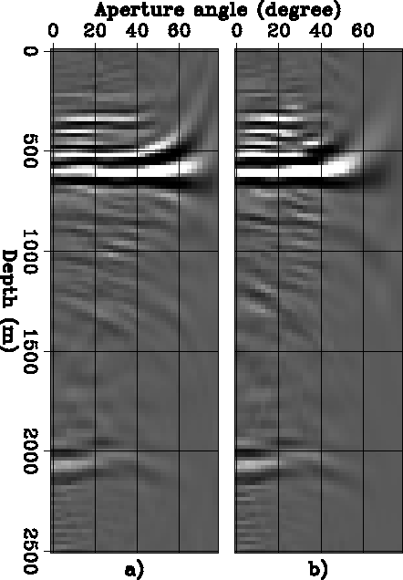 |
In 3-D, ADCIGs are five-dimensional objects,
and thus
it can be challenging
to gain an intuitive understanding of their behavior.
The next set of figures shows 2-D slices
of the 5-D space generated by computing 3-D ADCIGs
from the migrated cube obtained from a simple synthetic data set.
The data set
contains 5 dipping planes,
dipping at ![]() ,
, ![]() ,
, ![]() ,
, ![]() and
and
![]() toward increasing x and y.
The azimuth of the planes is 45 degrees
with respect to the direction of the acquisition.
The velocity is
toward increasing x and y.
The azimuth of the planes is 45 degrees
with respect to the direction of the acquisition.
The velocity is ![]() m/s,
which roughly corresponds to typical gradients found in the Gulf of Mexico.
The acquisition geometry had a single azimuth
oriented along the x axis,
and the maximum source-receiver offset was 3,000 meters.
Figure 7 shows the geometry of the reflectors.
The data were imaged with a full source-receiver 3-D prestack migration.
m/s,
which roughly corresponds to typical gradients found in the Gulf of Mexico.
The acquisition geometry had a single azimuth
oriented along the x axis,
and the maximum source-receiver offset was 3,000 meters.
Figure 7 shows the geometry of the reflectors.
The data were imaged with a full source-receiver 3-D prestack migration.
Because of the velocity gradient and the
oblique azimuthal orientation,
the azimuths of the reflections are not
equal to the azimuth of the acquisition (![]() ).
The reflection azimuths
are within the range of
).
The reflection azimuths
are within the range of ![]() and depend on the reflector dip and on the aperture angle
and depend on the reflector dip and on the aperture angle ![]() .The steeper the reflector dip
and the wider the aperture angle are,
the larger the azimuth rotation is
at the reflection point.
.The steeper the reflector dip
and the wider the aperture angle are,
the larger the azimuth rotation is
at the reflection point.
All the following figures show slices of the ADCIGs at
one fixed horizontal location with x=y=450 meters;
that is, they show slices through the
3-D image cube described as
ADCIG![]() .The most familiar of these slices
display the image as a function of the depth (z)
and the aperture angle (
.The most familiar of these slices
display the image as a function of the depth (z)
and the aperture angle (![]() ).
Figure 8 shows two
of these ADCIGs, for two different reflection azimuths:
).
Figure 8 shows two
of these ADCIGs, for two different reflection azimuths:
![]() degrees (panel a) and
degrees (panel a) and
![]() degrees (panel b).
The reflections from the deepest - and steepest -
reflector (
degrees (panel b).
The reflections from the deepest - and steepest -
reflector (![]() 1,430 meters)
are well focused within
the range delimited by these two azimuths.
In contrast, the reflections from the other two reflectors
(dipping at 30 and 45 degrees), are not well focused
at these azimuths, and thus they
frown downward even if the migration
velocity is correct.
1,430 meters)
are well focused within
the range delimited by these two azimuths.
In contrast, the reflections from the other two reflectors
(dipping at 30 and 45 degrees), are not well focused
at these azimuths, and thus they
frown downward even if the migration
velocity is correct.
Figure 9
shows a slice taken at the constant depth
of z=1,430 meters;
this depth corresponds to the deepest reflector.
The reflection amplitudes are thus shown as functions of
both the aperture angle (![]() )
and the reflection azimuth (
)
and the reflection azimuth (![]() ).
Because of the poor azimuthal resolution close to normal incidence,
the azimuthal range is wide for small
).
Because of the poor azimuthal resolution close to normal incidence,
the azimuthal range is wide for small ![]() ;it narrows around
;it narrows around ![]() degrees
as
degrees
as ![]() increases.
increases.
The increasing azimuthal resolution with aperture angle
is clearly demonstrated in
Figure 10.
The three panels in Figure 10
display the image as a function of
depth (z)
and reflection azimuth (![]() ),
and at constant aperture angle.
The aperture angles are:
a)
),
and at constant aperture angle.
The aperture angles are:
a) ![]() =4 degrees,
b)
=4 degrees,
b) ![]() =20 degrees, and
c)
=20 degrees, and
c) ![]() =30 degrees.
The curvature of the reflectors as a function of the azimuth
increases with increasing aperture angle,
indicating that the azimuthal resolution increases
as the aperture angle widens.
In other words,
the common-azimuth data ``illuminates'' all
the reflection azimuths for narrow aperture angles,
but ``illuminates'' only a narrow range
of reflection azimuths at wide aperture angles.
=30 degrees.
The curvature of the reflectors as a function of the azimuth
increases with increasing aperture angle,
indicating that the azimuthal resolution increases
as the aperture angle widens.
In other words,
the common-azimuth data ``illuminates'' all
the reflection azimuths for narrow aperture angles,
but ``illuminates'' only a narrow range
of reflection azimuths at wide aperture angles.
|
planes
Figure 7 Reflectors' geometry for the synthetic data set used to illustrated 3-D ADCIGs. The reflectors are slanted planes, dipping at | 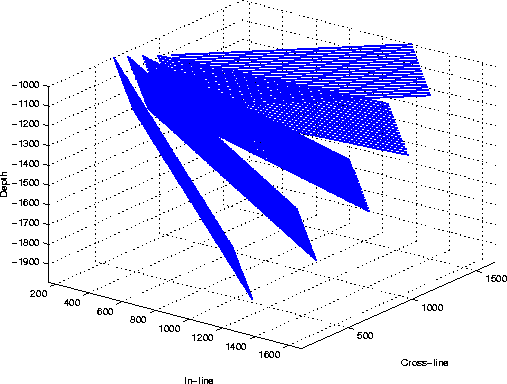 |
|
cig-1-data8
Figure 8 ADCIGs as functions of depth (z) and aperture angle ( |  |
|
zaz-60-60-dense-all-v4-data8
Figure 9 ADCIG as a function of aperture angle ( | 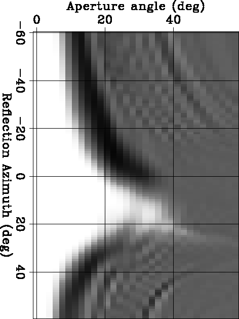 |
|
azim-gamma-all-data8
Figure 10 ADCIGs as functions of depth (z) and reflection azimuth ( | 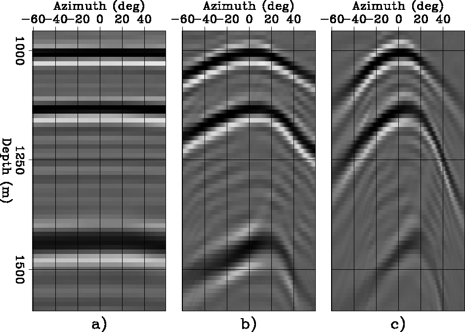 |