A trace with input offset vector ![]() and midpoint position
and midpoint position ![]() is first
transformed to its corresponding CCP position and zero offset. By defining the new
offset and azimuth position and by applying inverse PS-DMO, we transform the data to
a new CCP position and its corresponding CMP position.
is first
transformed to its corresponding CCP position and zero offset. By defining the new
offset and azimuth position and by applying inverse PS-DMO, we transform the data to
a new CCP position and its corresponding CMP position.
Here, we follow the same procedure as Biondi et al. (1998); Fomel and Biondi (1995) for the derivation of the PS-AMO operator.
First, we refer to equations (1) and (2) in order to understand the relationship between CMP and CCP for the 3D case. We rewrite equation (2) as
![]()
where ![]() is the angle between the midpoint vector (
is the angle between the midpoint vector (![]() ) and the transformation
vector (
) and the transformation
vector (![]() ).
).
We can then rewrite equation (1) as
| |
(5) |
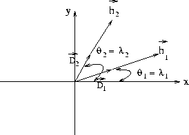
![]() is an extension of
is an extension of ![]() and lies in the CCP space. Figure 1
shows both
and lies in the CCP space. Figure 1
shows both ![]() and
and ![]() in the same plane. Since the vectors are parallel,
the angle between
in the same plane. Since the vectors are parallel,
the angle between ![]() and
and ![]() is the same as the angle between
is the same as the angle between ![]() and
and ![]() .If the coordinate system is
aligned with the midpoint coordinates, then the angle
.If the coordinate system is
aligned with the midpoint coordinates, then the angle ![]() is the same as the
azimuth (
is the same as the
azimuth (![]() ).
).
![]() changes after and
before PS-AMO. This variation is responsible for the event movement along
the common conversion point.
changes after and
before PS-AMO. This variation is responsible for the event movement along
the common conversion point.
|
rot
Figure 1 Definition of offset vector |  |
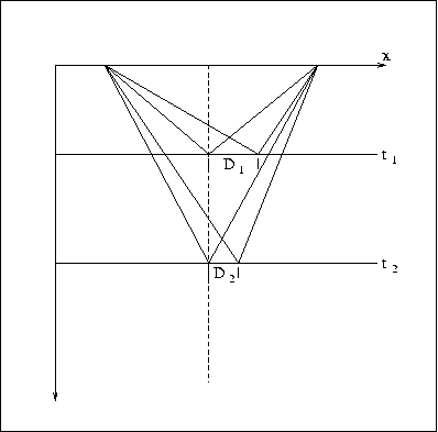
Figure 2 shows how event movement along CCP changes with depth. This
is due to the dependence of ![]() with respect to vp,
with respect to vp, ![]() and tn. This variance
with depth will persist even in a constant velocity media. Figure 2
also illustrates that the time after PS-AMO (t2) has a new
and tn. This variance
with depth will persist even in a constant velocity media. Figure 2
also illustrates that the time after PS-AMO (t2) has a new
![]() and
and ![]() , therefore, a new CCP position.
, therefore, a new CCP position.
|
plane2
Figure 2 Comparison between the CMP and CCP position in the PS-AMO operator |  |
Continuing with the procedure presented by Fomel and Biondi (1995)
to obtain the PS-AMO operator, we cascade PS-DMO [equation (5)] with its
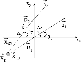
inverse. Figure 3 shows a scheme of the PS-AMO transformation.
A trace with input offset vector ![]() and midpoint at the
origin is transformed into equivalent data with output offset vector
and midpoint at the
origin is transformed into equivalent data with output offset vector ![]() and midpoint position
and midpoint position ![]() . The data is first transformed to
its corresponding CCP position and
. The data is first transformed to
its corresponding CCP position and ![]() . Subsequently, the
inverse PS-DMO repositions the data to a new midpoint position
. Subsequently, the
inverse PS-DMO repositions the data to a new midpoint position ![]() with a
new offset vector
with a
new offset vector ![]() .
.
|
plane
Figure 3 CMP-CCP plane, PS-AMO geometrical interpretation. |  |
The new trace position is defined by
 |
(6) |
Both ![]() and
and ![]() can be expressed as terms of the final midpoint position
can be expressed as terms of the final midpoint position
![]() by using the rule of sines in the triangle (
by using the rule of sines in the triangle (![]() ,
,![]() ,
,![]() )in Figure 3 as
)in Figure 3 as
 |
||
The final expression takes the form of
 |
(7) |
where
This expression represents the azimuth rotation in both the CCP domain and the CMP domain.