


Next: Examples of prestack imaging
Up: Biondi: Prestack reverse time
Previous: Examples of ADCIG to
One of the main advantages of
reverse-time migration methods
over downward-continuation migration methods is their
capability of imaging overturned events,
even in presence of lateral velocity variations.
However, this potential has not been exploited yet
for prestack migration for several reasons.
The computational cost is an important obstacle
that is slowly being removed by progress in computer technology.
In this section I will address two more fundamental problems.
First,
discrimination between image contributions from
reflections generated above an interface
from the image contributions from reflections
generated below the same interface.
These two reflections have usually opposite
polarities because they see the same
impedance contrast from opposite directions.
If their contributions to the image are simply
stacked together, they would tend to attenuate
each other.
Second, the updating of the migration velocity
from overturned reflections.
Solving the first problem is crucial
to the solution of the second one,
as graphically illustrated in
Figure 5.
This figure shows the raypaths for both events.
It is evident that the overturned event
passes through an area of the velocity field different
from the area traversed by the reflection from above.
The information on the required velocity corrections,
provided by the image obtained using a given velocity function,
can thus be inconsistent for the two reflections,
even showing errors with opposite signs.
imag-rays
Figure 5
Ray paths corresponding to the reflection generated above
the reflector and the one generated below the reflector.
The rays corresponding to the source wavefield are red
(dark in B&W),
lines represent the wavefronts
and the rays corresponding to the receiver wavefield are green.
(light in B&W),
|
|  |

The reflection from above and the reflection from below
can be discriminated by a simple generalization
of the imaging principle expressed in
equation (2),
that includes a time lag  in the crosscorrelation.
To understand this generalization it is useful to
review the process of image formation
in reverse time migration.
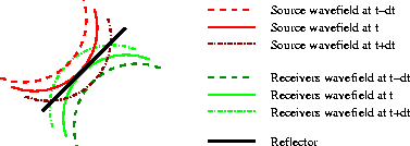
Figures 6-8
sketches this process at three different
values in the propagation time t.
For simplicity, the sketches represent the process
for the familiar reflection from above,
but similar considerations would hold
also for the reflection from below.
The reddish (dark in B&W) lines represent the wavefronts
for the source wavefield.
The greenish (light in B&W) lines represent the wavefronts
for the receiver wavefield.
At time t-dt
(Figure 6)
the two wavefronts do not intersect,
and thus they do not contribute to the crosscorrelation.
At time t
(Figure 7)
the two wavefronts begin to interfere,
and thus they begin to contribute to the image.
The contribution starts in the middle of the reflector
at time t,
and then it moves to the sides as the time progresses
to t+dt
(Figure 8).
The process described above correlates
the wavefields at the same time (t-dt, t, t+dt).
However, the wavefields can also be correlated at a non-zero lag
over the time axis.
In mathematical terms,
we can generalize equation (2)
as
|  |
(4) |
Now the image is function of an additional
variable  , that represents the correlation lag in time.
Figures 9-10
provide an intuitive understanding
of the outcome of the correlation
for
  (Figure 9)
and
 (Figure 10).
In both cases the two wavefields interfere and
they contribute to the image.
For negative
  the image is slightly above
the correct location of the reflector,
and
for positive
  the image is slightly below it.
Therefore, the image of the reflector slowly moves downward
(more precisely along the normal to the reflector)
as
  increases.
The crucial point is that for reflections generated from below,
this movement is in the opposite direction (i.e., upward).
This difference in propagation direction allows
an easy discrimination of the two reflections
by filtering the image
according to the propagation direction as
  progresses.
I have not implemented such a filtering yet,
but it should be relatively straightforward.
image-wave-st-m1
Figure 6
Wavefronts for
the source wavefield (red),
and
the receiver wavefield (green),
for three time steps (t-dt, t, t+dt).
The wavefronts at t-dt are highlighted in darker color.
The two highlighted wavefronts do not intersect,
and thus their contribution to the image is null.
|
| 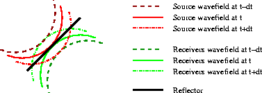 |

image-wave-st-0
Figure 7
Wavefronts as in
Figure 6.
The two highlighted wavefronts (time t) intersect in the middle of
the reflector,
and they contribute to the image at the intersecting point.
|
| 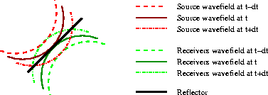 |

image-wave-st-p1
Figure 8
Wavefronts as in
Figure 6.
The two highlighted wavefronts (time t+dt) intersect at the edges
of the reflector,
and they contribute to the image at the intersecting points.
|
| 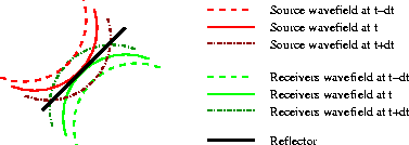 |

image-wave-lag-m1
Figure 9
Wavefronts as in
Figure 6.
The two highlighted wavefronts
(source wavefront at time t-dt
and the receiver wavefront at time t+dt)
intersect above the reflector,
and they contribute to the image at the intersecting point.
|
| 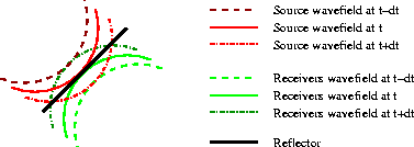 |

image-wave-lag-p1
Figure 10
Wavefronts as in
Figure 6.
The two highlighted wavefronts
(source wavefront at time t+dt
and the receiver wavefront at time t-dt)
intersect below the reflector,
and they contribute to the image at the intersecting point.
|
|  |

I have confirmed this intuitive understanding
by applying the generalized imaging condition
in equation (4)
to both the synthetic data set described above,
and a synthetic data set with overturned events.
I describe the results of the test on the latter in the next section.


Next: Examples of prestack imaging
Up: Biondi: Prestack reverse time
Previous: Examples of ADCIG to
Stanford Exploration Project
6/7/2002


