Francis Muir, Joe Dellinger, John Etgen, and Dave Nichols
This paper appeared in pages 1189 to 1193 of the September, 1992, GEOPHYSICS.
© 1992 Francis Muir, Joe Dellinger, John Etgen, Dave Nichols, and the SEG
(Click here to get quick access to all the figures and their captions.)
Geologists often see the Earth as homogeneous blocks separated by smoothly curving boundaries. In contrast, computer modeling algorithms based on finite-difference schemes require elastic constants to be specified on the vertices of a regular rectangular grid. How can we convert a continuous geological model into a form suitable for a finite-difference grid? One common way is to lay the finite-difference grid down on the continuous geological model and use whatever elastic constants happen to lie beneath each of the gridpoints.
Unfortunately, this simple sampling scheme can cause artifacts. For example, a smooth gently-sloping interface in the geological model translates into a coarse staircase on sampling, with long horizontal runs punctuated by occasional vertical steps. These artificial steps generate unwanted diffractions.
We apply S-M averaging to the gridding problem in a straightforward way. Lay the model grid down on the geological model as before, but this time consider not just each grid point, but the contents of a grid cell surrounding each point. Treat the contents of each cell as a stack of layers that can be averaged using the S-M calculus. This average set of elastic constants for the cell ought to be more representative than just whatever elastic constants happened to lie at the center. Also note that the average elastic constants calculated in this way depend not only on the contents of the cell but on the geometry of the contents as well.
Our model results show that this averaging method works surprisingly well. The price we pay is an increase in model complexity. For example, although the geological model itself may be everywhere isotropic, averaged grid cells at dipping layer boundaries will have transversely isotropic symmetry with the axis tilted normally to the layer boundary.
Historically, the acoustic or elastic wave equation was solved on a discrete grid using first or second-order differencing in time and space (Kelly et al., 1976). These methods were only accurate if the modeled frequencies remained well below the spatial and temporal Nyquists, in which case almost any interpolation method used to construct the model grid would work well enough. In recent years the situation has changed. The pseudo-spectral method (Kosloff et al., 1985) can compute spatial derivatives accurate up to Nyquist; Edwards et al. (1987) show how a new time-update method due to Tal-Ezer (1986) can additionally eliminate time-derivative discretization errors as well. These new high-accuracy modeling methods are efficient because they allow the wave field to be coarsely sampled. Unfortunately, the velocity model is then coarsely sampled as well. The interpolation method used to construct the model grid becomes important.
There are ways of avoiding this drawback. One way is to use finite-element methods, which can discretize the model using elements that follow the geologic boundaries. Fornberg (1988) introduced another solution, a mapping method that converts a curved-grid model into a flat (or step) layered computational model that can be accurately represented on a rectangular grid.
The main attraction of the explicit finite-difference methods on standard rectangular grids is their efficiency and simplicity. Finite-element methods or other distorted-grid methods require complicated setup steps to incorporate the local geometry into the equations, while the simpler rectangular-grid methods only need easily-specified 2-D or 3-D arrays of values. Our model representation allows for a better representation of dipping interfaces, without giving up the simplicity of a regular grid.
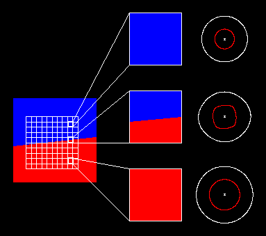
The top highlighted cell is entirely within the top medium. Its elastic constants are therefore the same as that of the top (light-shaded) homogeneous medium. To the right of the blown-up cell we show the isotropic P-SV impulse response for this medium. The bottom highlighted cell is entirely in the lower medium, and so its elastic constants are the same as that of the lower (dark-shaded) homogeneous medium. Again, to the right we show the isotropic P-SV impulse response. The middle highlighted cell is the interesting one, since it contains a mixture of both media. Intuitively, the elastic constants for this cell should be some sort of average of the top and bottom media. The question is, what sort of averaging is best?
One obvious way is to average each elastic constant independently. This method is somewhat better than simply choosing one component medium or the other, but it is still not very satisfactory. (It does not even get the kinematics right for the simplest of cases!)
A much better way is to average the slownesses, weighted according to the volume of each medium in the cell. This method at least gets the kinematics right for the obvious cases, and seems to work very well in practice if the two media being averaged are both isotropic and are not too different in their elastic properties. This slowness averaging method is still not the best. If the layers are not isotropic the method becomes undefined. (What are ``the'' slownesses to average?) If the elastic properties of the media are too divergent the assumption that the P and S properties can be averaged independently breaks down. (We will show an example of this later in Figure 3.) Most importantly, this method cares nothing for the geometry of the layers within the cell, which we know must have some bearing on the answer.
We will perform the average a more sophisticated way, by considering the cell to be a bit of a tilted layered medium, with the proportions of each of the two media set in accordance with the area of each in the grid cell. We can then use the S-M calculus to find the homogeneous equivalent to this particular tilted layered medium. (Note that Backus and Postma averaging are just special cases of S-M averaging; since S-M also provides the most convenient formalism, there is no reason not to use it even in the standard isotropic case.) The middle rightmost part of Figure 1 shows the P-SV impulse response that results if this S-M averaging method is used for the sample middle cell. Note the resulting medium is not isotropic, which would have been the case if the P and SV slownesses had been averaged independently. It is transversely isotropic with an axis of symmetry normal to the tilted layer boundary within the cell. This anisotropy incorporates information about the geometry of the layer boundary within the cell.
In the S-M calculus (Schoenberg and Muir, 1989) layers are parameterized by their thickness, density, and a 6-by-6 (compressed subscript notation) stiffness tensor. This defines the fundamental unit to be operated on; it can be encoded in one of three ways. The symmetric 6-by-6 matrix can be rearranged to give three 3-by-3 submatrices; we call the 6-by-6 form the parameter form and the three 3-by-3 matrix form the model form. (This change is merely a reordering of elements.) Layer parameters are mapped from the model form to a group domain using 3-by-3 matrix operations, as does the inverse mapping from group back to model. Layers can be combined by simple addition of elements in the group domain. So we need one pair of utilities to transform between the three basic representations, and one to add the units in the group domain element by element. The only other utility we need for our application is rotation of the coordinate frame of the elastic constants of a layer. This is done by expanding the 6-by-6 parameter form to its full 3-by-3-by-3-by-3 tensor form, applying a 3-by3 rotation operator, and converting back to the standard parameter form.
To find the elastic constants for a boundary grid cell, rotate the coordinate frame so that the z-axis is normal to the boundary. Use the group domain to add the two bounding media in the appropriate volume ratio, and then rotate the result back to the original coordinates. (This leaves the problem of multiple layers with nonparallel dips untackled, but that is a refinement for the future.)
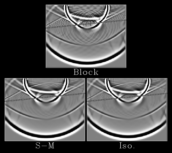
The model consists of one homogeneous isotropic medium over a somewhat faster one (the model is just a scaled-up version of the one depicted in Figure 1). The model grid consists of 243 by 243 gridpoints, with dx=dz=.75. The bottom 53 gridpoints of the model are not shown. The top of the model is a free surface; strips 30 gridpoints wide at the left and right edges form absorbing boundaries. (The direct P can be seen to reflect slightly off the absorbing regions in the plots, and also to slightly wrap around). The source is a vertical (z) point force, located 3 gridpoints under top center. The vertical component of displacement is shown. The source emanates a second-derivative Gaussian wavelet with a fundamental frequency of .25; dt=.06. The upper medium has elastic constants density = 1., C11 = 4.41, and C44 = .81 (isotropic). The lower medium has elastic constants density = 1.25, C11 = 8.45, and C44 = 2.45 (isotropic). The slope of the interface is $1/10$. (Note all dimensions given above are in arbitrary but consistent units.)
The top part of Figure 2 shows the results if we follow the usual practice and fit a best-approximating set of stair steps to the interface. The step every 10 horizontal gridpoints causes very noticeable diffractions in the scattered wavefield. The lower left part of Figure 2 shows the same example using our Schoenberg-Muir averaging scheme. The S-M model nearly eliminates the stair-step scattering. The lower right part of Figure 2 shows the same example again, this time using isotropic slowness averaging. This method reduces the stair-step scattering almost as well as the S-M interpolation method.
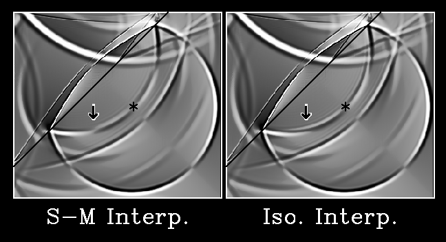
The model is similar to that in the previous example, except the grid is 375 by 375 (80 gridpoints at the bottom and 45 gridpoints at the right edge are omitted from the plot), the source has a fundamental of .3, and the layer boundary has a slope of 1. The source is a point force directed towards the upper left (directly at the boundary). The upper right component of displacement (parallel to the boundary, perpendicular to the source direction) is shown. The upper left medium has elastic constants density = .5, C11 = 8., and C44 = .32 (isotropic). The lower right medium has elastic constants density = 1., C11 = 16., and C44 = 5.76 (isotropic).
As can be seen in Figure 3, the S-M method of interpolation does a better job of reproducing the true amplitude-versus-offset behavior of the reflected S-S wave, correctly generating a clean sign change at the critical angle. (The isotropic averaging method instead performs a fuzzy sign change via an extended phase shift.) The isotropic slowness averaging method fails for this case because there is substantial interaction between the P and S components of the wavefield at the interface; the assumption that the P and S behaviors can be treated independently has broken down. While isotropic slowness averaging does conserve vertical travel times, the appeal of this method is based on ray-theoretic considerations that are inappropriate on scales small compared to the wavelength.
The importance of this can be seen in Figure 1; C15 is zero in both of the isotropic homogeneous media, but it is far from zero in the tilted-axis transversely isotropic medium necessary to represent the border grid cells. No sampling method that considers each elastic constant independently could have produced this result. Any such method (for example, isotropic slowness averaging) would find a zero value for C15.
The strength of our method can also be viewed as a drawback: an averaged elastic tensor may be more anisotropic than those of the individual layers. In particular, as we mentioned in the previous paragraph, an average of two differing isotropic materials will not be isotropic. In the long term, as the use of anisotropic models becomes more common, this should not be a problem. If we always used modeling schemes that allowed for a general Hooke's Law relation with a complete set of elastic constants, like the one we used to make Figures 2 and 3, no extra complexity would ever be added.