|
zeroFoltRaw
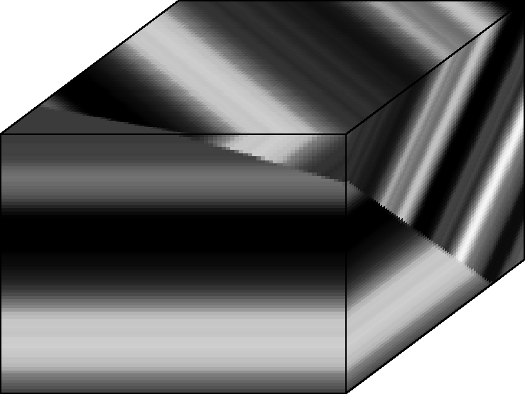
Figure 4 Synthetic fault image volume. Two sedimentary layer packages of different dip are separated by a fault without fault reflection. This image serves as an idealized test case for this chapter's discontinuity attributes. |  |
To illustrate individual discontinuity attribute computations, I will apply them to one synthetic and two seismic image volumes. The synthetic image of Figure 4 simulates a simple fault without fault reflection. The image cube shows two distinct regions. One region is filled with a horizontal plane wave, the other with a dipping plane wave. The contact plane between the two regions models a subsurface fault. An ideal corresponding discontinuity attribute map is zero everywhere but along the fault plane.
|
zeroFoltRaw
Figure 4 Synthetic fault image volume. Two sedimentary layer packages of different dip are separated by a fault without fault reflection. This image serves as an idealized test case for this chapter's discontinuity attributes. |  |