Azimuth moveout correction relies heavily on shape of the operator used in the application. Since these
operators are convolved with the data their shapes and sizes may significantly influence the output of the
operation. The time shift to be applied to the data is a function of
the difference vector ![]() between the midpoint of the input trace and the
midpoint of the output trace.
The impulse response of the AMO operator in isotropic media
has a general skewed saddle shape. In fact, for homogeneous isotropic media,
the shape of the saddle is given by the following analytical equation
between the midpoint of the input trace and the
midpoint of the output trace.
The impulse response of the AMO operator in isotropic media
has a general skewed saddle shape. In fact, for homogeneous isotropic media,
the shape of the saddle is given by the following analytical equation
| |
(1) |
 |
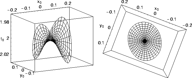
Figure 1 shows a side and a top view of the 30-degrees correction AMO operator for an isotropic homogeneous medium. It is clearly 3-D in structure and has a general skewed saddle shape. The saddle is altered 30 degrees from the inline direction, in agreement with the amount of azimuth correction applied. The AMO operator domain has an overall circular shape. The shape of this AMO domain appears to be different from the one presented by Biondi et al. (1998) (a parallelogram), because I limit the zero-offset ray parameters when plotting the AMO operator.
Alkhalifah and Biondi (1998) generated AMO operators for isotropic v(z) media. They used a nifty approach to build their AMO operators for v(z) media. A similar approach is used here, but discussed below, to build the anisotropic AMO operators.
 |
Figure 2 shows a side and a top view of the 30-degrees correction AMO operator for a v(z) medium, in which velocity increase with depth linearly as v(z)=1.5+0.6 z km/s, where z is the depth given in km. Again, the saddle is altered 30 degrees from the inline direction, in agreement with the amount of azimuth correction applied. The root-mean-square (rms) velocity for this model is similar to the homogeneous one and is equal to 2 km/s. Clearly, the v(z) operator is very similar in shape and size to the homogeneous one, shown in Figure 1. Thus, Alkhalifah and Biondi (1998) concluded that the influence smooth velocity variations on the AMO operator is small.