


Details of solving the eikonal equation using the fast marching method in Cartesian coordinates can be found in Cao and Greenhalgh (1994) and Sethian (1996), while its application in spherical coordinates can be found in Alkhalifah and Fomel (1997). A summary of the approach, however, is revisited below.
The first-order nature of the fast marching method results in large errors for conventional sparse grid-point configurations. The largest of these errors occur when the curvature of the wavefront is large and the wavefront is traveling diagonally with respect to the orthogonal coordinate system. However, if the wavefront curvature is zero, or the wavefront is parallel to the coordinate system, the fast marching method becomes exact. For waves emanating from a point source, large errors appear in the Cartesian coordinate implementation of the method at angles of 45 degrees from the vertical, especially near the source, where the wavefront curvature is large. Plane waves, on the other hand, are calculated exactly in the Cartesian-coordinates, because in such coordinates plane waves have no curvature.
In spherical coordinates (Figure 1),
waves emanating from a point source are effectively propagated as plane waves
on a regular grid. For
homogeneous media, these plane waves have fronts that are always parallel to
the ![]() -
-![]() plane. As a
result, traveltime calculation using the fast marching approach in
spherical coordinates is always exact in homogeneous media Alkhalifah and Fomel (1997).
plane. As a
result, traveltime calculation using the fast marching approach in
spherical coordinates is always exact in homogeneous media Alkhalifah and Fomel (1997).
|
polar-dif
Figure 1 A spherical coordinate system given by r, | 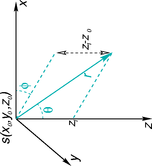 |

|
march-pol
Figure 2 The steps taken to implement the fast marching in polar coordinates. Black circles imply computed traveltimes that are set because of their minimum traveltime value along the front. Gray circles constitute the front of the wave, and they are stored in the wavefront heap array and sorted from minimum to maximum traveltime value. The traveltime is schematically given by the size of the circle; the larger the radius, the greater the traveltime. The minimum is always extracted first from the heap array at each step, its traveltime is set (given a black circle), and all surrounding grid points that are not set are computed and put into the heap array. We precede until all grid points are computed and set. | 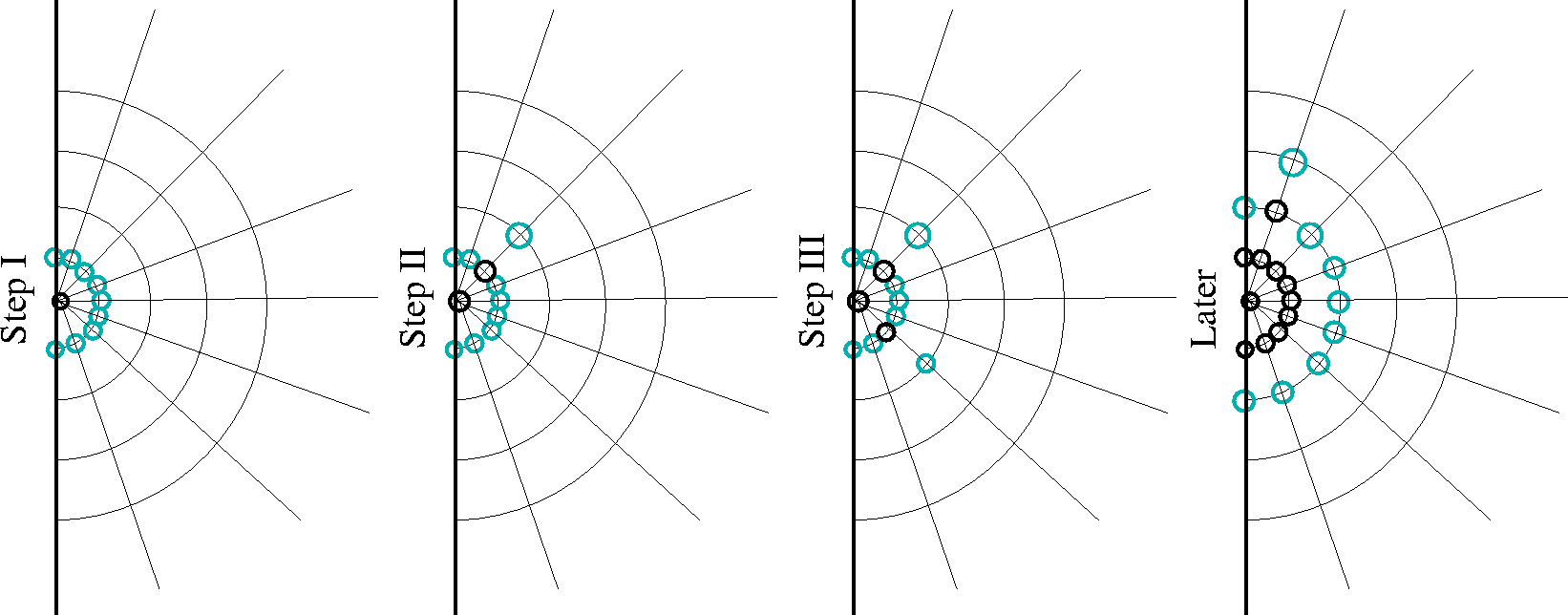 |
Figure 2 shows schematic plots of
the progress of this method along a 2-D polar coordinate grid.
The source is computed initially
and set to zero for all angles ![]() . When
stretched on a regular grid, all points at the
surface r=0 are set to zero. These points are inserted in the wavefront array and
sorted from minimum
traveltime to maximum. In the case of the source grid point, the sorting
step is unnecessary because all traveltimes
are equal to zero. The minimum is then extracted, and the traveltimes for neighboring grid points are
computed using the following relation:
. When
stretched on a regular grid, all points at the
surface r=0 are set to zero. These points are inserted in the wavefront array and
sorted from minimum
traveltime to maximum. In the case of the source grid point, the sorting
step is unnecessary because all traveltimes
are equal to zero. The minimum is then extracted, and the traveltimes for neighboring grid points are
computed using the following relation:
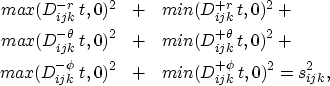 |
||
| (1) |
![]()
![]()
![]()
![]()
![]()
![]()
Using fast
algorithms (heap sorting), the sorting part of the fast marching algorithm can be maintained at a computational
cost proportional to ![]() , where N is the number of grid points
in the computational domain. As a result, the cost of the eikonal
solver is roughly proportional to
, where N is the number of grid points
in the computational domain. As a result, the cost of the eikonal
solver is roughly proportional to ![]() . This efficiency feature is maintained in spherical
coordinates as well. The cost of transforming traveltime information from
spherical coordinates to Cartesian ones
is proportional to N, and thus is less significant.
. This efficiency feature is maintained in spherical
coordinates as well. The cost of transforming traveltime information from
spherical coordinates to Cartesian ones
is proportional to N, and thus is less significant.
 |
 |