


We build the AMO operator in v(z) media by cascading a forward and an inverse 3-D v(z) DMO operators. An angular transformation, that depends on the azimuth correction, is applied to the inverse operator. Therefore, to build the AMO operator we must first build the 3-D v(z) operator. Artley et al. (1993) suggested an approach to build a kinematically exact 3-D DMO operator. Following their approach, we construct the 3-D DMO operator by solving a system of six nonlinear equations to obtain six unknowns that include, among other things, the zero-offset time and surface position of the specular reflection point. Artley's traveltimes are calculated and tabulated using an isotropic v(z) ray tracing. Because velocity varies only vertically, each ray propagating in the subsurface is contained in a vertical plane; therefore, 2-D raytracing is sufficient to calculate the traveltimes. The total traveltime is:
tsg = ts+tg,
and therefore the gradient vector,![]()
| |
(2) |
![]()
![]()
![]()
![]()
![]()
| |
(3) |
Substituting equation (3) into the x-and y-components of equation (2) provides two of the six nonlinear equations needed to be solved.
The other four equations are:
 |
(4) | |
| (5) | ||
| (6) | ||
| (7) |
Equation (4) is the requirement that the surface distances, ![]() , along the inline component from both the source and receiver to the specular
reflection point (SRP) add to equal the source-receiver offset, 2h.
Equation (5) is the requirement that the distances
along the crossline component to the SRP are equal for the source and receiver.
Equations (6) and (7) imply that the vertical times,
, along the inline component from both the source and receiver to the specular
reflection point (SRP) add to equal the source-receiver offset, 2h.
Equation (5) is the requirement that the distances
along the crossline component to the SRP are equal for the source and receiver.
Equations (6) and (7) imply that the vertical times, ![]() from the source, the receiver, and the zero-offset
surface positions to the SRP are equal.
Both
from the source, the receiver, and the zero-offset
surface positions to the SRP are equal.
Both ![]() and
and ![]() are calculated using ray tracing and
then stored in a table as a function of ray parameter p
and the traveltime t.
are calculated using ray tracing and
then stored in a table as a function of ray parameter p
and the traveltime t.
The inverse operator is calculated in the same way as the forward operator, but now we must calculate tn or the total traveltime tsg instead of t0, which is known. Subsequently, x0 and y0 are calculated in the same way as the forward approach.
To build the AMO operator, the output of the forward 3-DMO operator t0(tn,px,py), x0(tn,px,py), and y0(tn,px,py) are inserted into the inverse 3-D DMO operator. Prior to applying the inverse operator the axes are rotated with an angle given by the desired azimuth correction. The result is an AMO operator given by
tAMO[t0(tn,px,py),px,py],
xAMO(tn,px,py)=x0(tn,px,py)-x0,(t0,px,py),
andyAMO(tn,px,py)=y0(tn,px,py)-y0,(t0,px,py),
where x0, and y0, correspond to the adjoint (inverse) operator in the rotated domain. The rotation angle is the azimuth correction angle.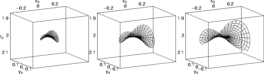 |

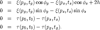
Figure 3 shows three AMO operators that correspond to three different azimuth correction angles in a v(z) medium. From left to right, the azimuth correction angles are 15, 30, and 45 degrees, respectively. The input and output offset are the same and equal to 2 km. The root-mean-square (rms) velocity for this model is similar to the homogeneous one and is equal to 2 km/s. Interestingly, these operators are very similar to the respective homogeneous ones. The subtle differences, however, will be apparent when we generate the residual AMO operators. Though the shape of the AMO operator is practically the same between the three corrections, the size is very much dependent on the amount of azimuth correction; the larger the azimuth angular correction the larger the AMO operator. This phenomenon occurs for homogeneous as well as v(z) media. As a result, we will use a single azimuth correction for most of the examples shown in this paper, that is a 30 degrees azimuth correction.
 |
Figure 4 shows an upper side and a top view of the 30-degrees correction AMO operator for the v(z) medium. The saddle is altered 30 degrees from the inline direction, in agreement with the amount of azimuth correction applied. The AMO operator domain has an overall circular shape. The shape of our AMO domain appears to be different from the one presented by Biondi et al. (1998) (a parallelogram), because we limit the zero-offset ray parameters when plotting the AMO operator.