|
salt
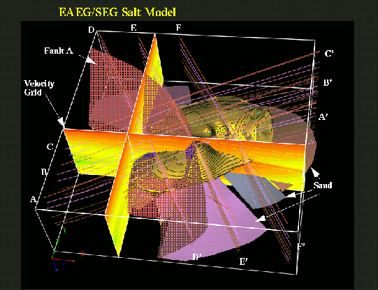
Figure 1 3-D representation of the SEG-EAGE salt model. |  |
The main motivation for applying partial stacking instead of global stacking is to improve the final image when the velocity function does not fulfill the simple assumptions at the basis of the conventional normal moveout (NMO) and DMO process. After partial stacking the data size is considerably reduced, but the results are still segregated by offset ranges. Usually the output of partial stacking is organized in pseudo common-offset cubes, that can be imaged in several ways. For time-imaging purposes, one common procedure is to apply zero-offset migration to each pseudo common-offset cube and then apply a residual NMO correction before stacking Ferber et al. (1996). Another common practice is to transform the pseudo common-offset cubes into true common-offset cubes by inverse DMO Canning and Gardner (1996); Ronen (1987). These common-offset cubes can then be imaged by a full prestack depth migration or prestack time migration. Other than to reduce the cost of prestack migration for structural imaging, partial stacking after DMO is also commonly used for AVO analysis, specially in the Gulf of Mexico. The AVO trend is usually measured from the common-offset cubes after migration has focused the diffractions and correctly positioned the amplitude anomalies.
The accuracy of partial stacking after DMO depends on the degree of velocity variations in the subsurface, both vertical and lateral. For partial stacking to enhance reflections and suppress noise, reflections need to be coherent across the traces to be stacked. Hale and Artley 1993 and Hawkins et al. 1995 showed that even in a simple vertically layered medium constant-velocity DMO is not accurate in correcting the kinematics of dipping reflectors. Although partial stacking is less sensitive than global stacking to velocity variations because the offset range is narrower, nevertheless it is not compleatly insensitive. The accuracy of the partial stacking process is particularly important for AVO applications. Uncoherent stacking caused by small relative shifts between the traces is sufficient to alter the AVO response of dipping events Rietveld et al. (1997).
Partial stacking after azimuth moveout (AMO) is an alternative to partial stacking after DMO. Biondi et al. 1998 defined AMO as the operator that is equivalent to the the chain of DMO followed by inverse DMO. In this paper I demonstrate that, when the velocity increases with depth, partial stacking after AMO is more accurate than partial stacking after constant-velocity DMO. I also show an example in which partial stacking after AMO is less sensitive than partial stacking after constant-velocity DMO to a large lateral increase in the NMO velocity function. Although AMO and DMO are strictly related, the two processes that I compare yield different results because the domains in which the data are partially stacked are different. The data are stacked in the zero-offset domain after DMO, but the data are stacked in the finite-offset domain after AMO. AMO has the intrinsic advantage over DMO to be only a residual transformation. It transforms the data from one finite offset to a nearby finite offset; in contrast, DMO transforms the data all the way to zero offset. Therefore, the AMO operator moves the dipping events along the midpoint directions less than the DMO operator does, and it is consequently less sensitive to deviations from the underlying assumption of constant velocity.
Several authors presented generalizations of DMO to depth-variable velocity functions Dietrich and Cohen (1993); Hale and Artley (1993); Hawkins et al. (1995); Meinardus and Schleicher (1993); Perkins and French (1990); Popovici (1990); Sun and Alkhalifah (1998); these V(z) DMOs could be used in place of constant-velocity DMO to improve the accuracy of partial stacking. One important drawback of V(z) DMOs is that they are quite sensitive to the accuracy of the input velocity function. Another drawback is that the V(z)-DMO operators often have cusps and triplications. These singularities make the implementation of V(z) DMO as integral operators prone to artifacts and/or computationally intensive. Because it is a residual operator, AMO is spatially compact and inexpensive to apply. The impulse response is a skewed saddle and is single valued, though its implementation as integral operator requires some care Biondi et al. (1998). A V(z) AMO operator can also be derived by cascading V(z) DMO with its inverse Alkhalifah and Biondi (1998). Alkhalifah and Biondi 1998 show that, whereas the V(z) AMO operator may have triplications, it in general a better behaved operator than the V(z) DMO operator.
Furthermore, to my knowledge, no implementation of inverse V(z) DMO has been presented in the literature yet. Therefore, some of the most advanced uses of DMO coupled with inverse DMO, such as prestack depth migration after partial stacking Biondi (1997); Mosher et al. (1997), and spatial dealiasing Brink et al. (1997); Ronen (1987) cannot exploit the improved accuracy of V(z) DMO.
In this paper I will only show the results of comparing partial stacking after DMO and AMO; Biondi et al. 1998 developed the theory of AMO. For my tests, I use the subset of the SEG/EAGE salt data set Aminzadeh et al. (1996) known as C3 Narrow-Azimuth classic data set (C3-NA) 1997. The data were recorded on the realistic and complex salt-dome structure shown in Figure 1.
|
salt
Figure 1 3-D representation of the SEG-EAGE salt model. |  |