The fast marching method for numerically solving the eikonal equation is described in detail in Cao and Greenhalgh (1994) and Sethian (1996). In this section, we give a summary, as well as point out some of the advantages and drawbacks, of the approach.
Starting from a point source (we can also start with a plane or any closed surface of sources), we calculate the traveltime at the surrounding grid points analytically. Obtaining initial analytical solutions is necessary to reduce some of the first-order numerical errors, discussed in detail below. The original point source is set; that is its traveltime cannot be updated. The new traveltimes of the surrounding grid points are put in an array that constitutes the wavefront and are sorted from minimum to maximum traveltime values. The minimum traveltime, which is in front of this array, is extracted first, its value is set (cannot be updated), and all neighboring unset grid points are updated using the following formula Sethian (1996):
where Dij-x is the derivative of traveltime with respect to x at grid point i, j, k given by
![]()
![]()
|
march-cart
Figure 2 The steps taken to implement fast marching in Cartesian coordinates. Black circles imply computed traveltimes that are set, because of their minimum nature, at the time of extraction from the heap array. Gray circles constitute the front of the wave, and they are stored in the wavefront heap array and sorted from minimum to maximum traveltime value. The traveltime is schematically given by the size of the circle; the larger the radius, the greater the traveltime. The minimum is always extracted first from the heap array at each step, its traveltime is set (given a black circle), and surrounding grid points that are not set are computed and inserted into the wavefront heap array. We precede until all grid points are computed and set. | 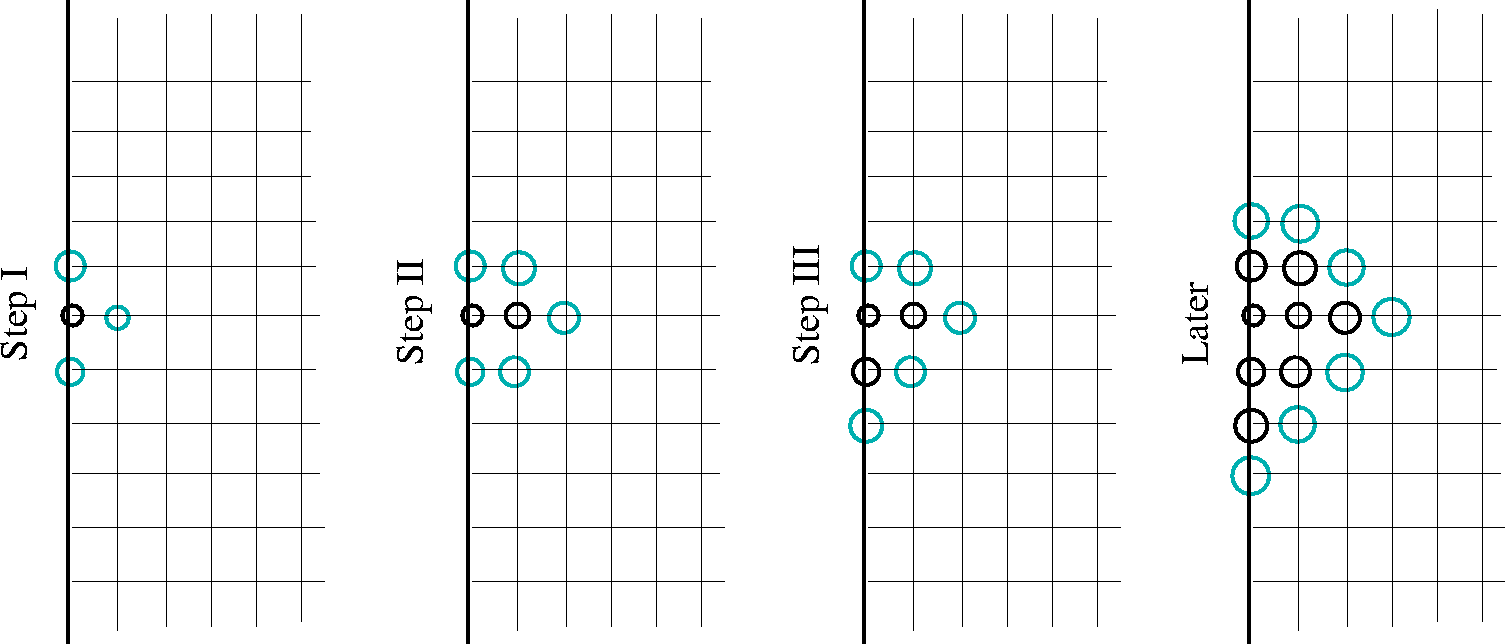 |

Figure 2 shows schematic plots of the progress of this method along a 2-D Cartesian grid.
|
ABCD
Figure 3 A simple Cartesian-coordinate grid configuration. In this model, the slowness equals 1. Grid A is set, and B is the minimum traveltime along the front that includes B and C. We then compute D as a neighbor of B. | 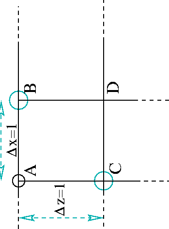 |
The first-order nature of the fast marching method results in large errors for conventional
sparse grid-point configuration. The largest of these errors occur at the first step of computation. To
demonstrate, let us consider a simple example where the wave slowness is 1 km/s, and the grid spacing is 1 km.
From Figure 3, the grid point A is the location of the source and its traveltime is,
as a result, set to zero.
Grid points B and C are part of the front with traveltimes accurately calculated at B and C (for both t=1).
Grid point B is extracted from the wavefront array and used to calculate the
traveltime at D
based on equation (4). As a result, the traveltime at
D equals ![]() instead of the true value of
instead of the true value of
![]() . This difference corresponds to about 20 percent error
in the traveltime calculation at D. It is also probably the maximum error
allowed by this scheme, which occurs here because of the 45-degree wavefront propagation
angle and the high
wavefront curvature (near the
source). This 20 percent error is always associated with the computation of traveltimes for the
first layer of grid points
around the source grid point. The next layer of grid points should have lower relative errors.
If a plane wave (that is, with no curvature) passes through the same grid points in Figure 3
at a 45-degree wavefront propagation angle, the traveltime at D computed
using equation (4) equals
. This difference corresponds to about 20 percent error
in the traveltime calculation at D. It is also probably the maximum error
allowed by this scheme, which occurs here because of the 45-degree wavefront propagation
angle and the high
wavefront curvature (near the
source). This 20 percent error is always associated with the computation of traveltimes for the
first layer of grid points
around the source grid point. The next layer of grid points should have lower relative errors.
If a plane wave (that is, with no curvature) passes through the same grid points in Figure 3
at a 45-degree wavefront propagation angle, the traveltime at D computed
using equation (4) equals ![]() , which is accurate.
Therefore, the amount of wavefront curvature with respect to the
grid is another factor that affects the size of the error.
As we propagate away from the source, the percentage of error reduces considerably.
One way to avoid errors near the source is
to compute the traveltime analytically at grid point D, and
delay starting the fast marching algorithm until
after computing the first group of grid points surrounding the source.
, which is accurate.
Therefore, the amount of wavefront curvature with respect to the
grid is another factor that affects the size of the error.
As we propagate away from the source, the percentage of error reduces considerably.
One way to avoid errors near the source is
to compute the traveltime analytically at grid point D, and
delay starting the fast marching algorithm until
after computing the first group of grid points surrounding the source.
However, such first-order errors will always exist, as we will see in the numerical examples, regardless of how we compute the initial set of points. One way to reduce such errors, yet retain the main features of the method, is to using the spherical coordinate system, as we will see in the next section.