To demonstrate some of the features of this additional
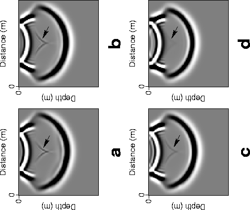
wave type (the artifact in Figure 2), Figure 4
shows a snapshot
taken at 0.13 s of the finite-difference solution of the acoustic VTI wave equation
for a two-layered model with the interface at depth 100 m. The first layer is isotropic with
velocity equal 1500 m/s, and the second layer is VTI with velocity equal to 2000 m/s and
![]() =0.1. In Figure 4a, the source is placed
on the boundary between the isotropic and VTI layers at depth 100 m. As a result, no artifact appears
in the
isotropic layer, whereas the artifact is clearly apparent in the VTI layer. In
Figure 4b, the source is placed in the isotropic layer at depth 95 m from the
surface. The resulting
additional wave is weaker than in the previous case,
where the source was directly interacting with the VTI layer. A
greater distance between the source and the VTI layer, as in Figures 4c
and 4d, causes the artifact to decay. In fact, when the source is placed
at depth 80 m (Figure 4d), only 20 m from the VTI layer, the additional wave practically
disappears.
=0.1. In Figure 4a, the source is placed
on the boundary between the isotropic and VTI layers at depth 100 m. As a result, no artifact appears
in the
isotropic layer, whereas the artifact is clearly apparent in the VTI layer. In
Figure 4b, the source is placed in the isotropic layer at depth 95 m from the
surface. The resulting
additional wave is weaker than in the previous case,
where the source was directly interacting with the VTI layer. A
greater distance between the source and the VTI layer, as in Figures 4c
and 4d, causes the artifact to decay. In fact, when the source is placed
at depth 80 m (Figure 4d), only 20 m from the VTI layer, the additional wave practically
disappears.
 |
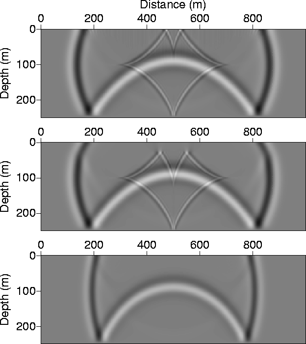
Putting the receivers in the isotropic layer all but assures that no such artifacts appear on synthetic sections. The basic concept is that these waves do not travel in the isotropic layer. Figure 5 shows snapshots of the wavefield for a VTI homogeneous model (top section), a VTI model with a thin isotropic layer of 25 m thickness at top (middle section), and a purely isotropic homogeneous model (bottom section). All three models have a constant velocity of 2000 m/s. As shown earlier, the artifact, illustrated by the diamond shaped wave, appears only when the medium is VTI, as is the case with the top two sections. However, this wave does not travel in the thin isotropic layer in the middle section; it actually reflects at the isotropic-VTI boundary. Therefore, by placing the geophones in this thin isotropic layer, we can avoid recording the artifact.
 |
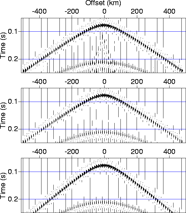
Figure 6 shows common-shot gathers corresponding to the models described in Figure 5. The horizontal line of receivers, in all cases, are placed at depth 10 m from the surface. Therefore, for the VTI model case with the thin isotropic layer (middle section), the artifact, which is apparent for the purely VTI model, disappears. The wave traveltimes, on the other hand, are barely affected by this thin isotropic layer. The purely isotropic model (bottom section) results in slower wave arrival times than those in the VTI models. The wavelet peak frequency of 35 Hz, used in these examples, is typical of surface seismic survey frequencies used nowadays.
 |