The solutions to the focusing eikonal can be computed using current methods for solving the standard eikonal, either directly by modern eikonal solvers Fomel (1997); Sethian and Popovici (1997), or by ray tracing. We chose a ray tracing solution, because for reflection tomography is handier to have rays than traveltime maps.
To derive the ray-tracing system for the focusing eikonal
we begin by writing its associated Hamiltonian as
a function of the ray parameters ![]() and
and ![]() ,
,
| (10) |
The associated ray-tracing equation are:
Rays can be traced in ![]() by solving the ray-tracing equations
in (11)
by a standard ODE solver.
The appropriate initial conditions for
the ray parameters
by solving the ray-tracing equations
in (11)
by a standard ODE solver.
The appropriate initial conditions for
the ray parameters ![]() and
and ![]() when the source is at
when the source is at ![]() and the take-off angle is
and the take-off angle is ![]() are:
are:
To test the accuracy of our derivations we numerically
solved the ray tracing equations (11)
for a heterogeneous velocity function,
and compared the results with
a ray-tracing solution of the standard eikonal equation.
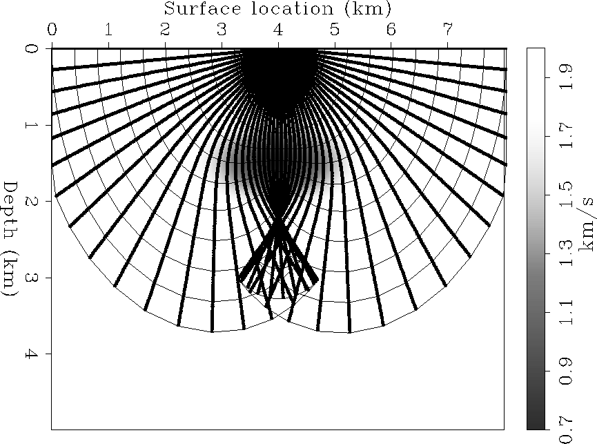
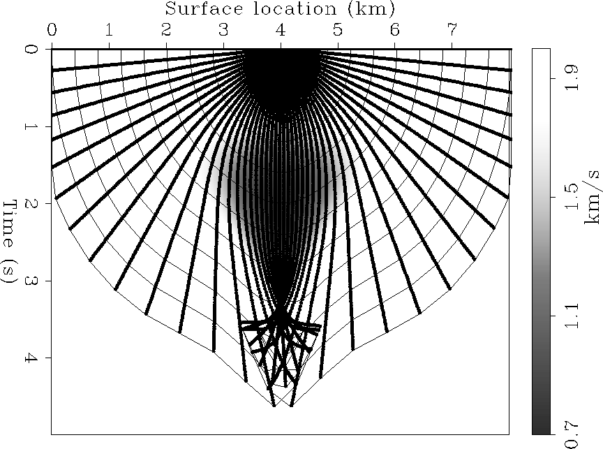
As expected, ![]() -rays map exactly into z-rays,
for all velocity fields.
Figure
-rays map exactly into z-rays,
for all velocity fields.
Figure ![[*]](http://sepwww.stanford.edu/latex2html/cross_ref_motif.gif) and
Figure
and
Figure ![[*]](http://sepwww.stanford.edu/latex2html/cross_ref_motif.gif) show an example of the ray field
when the velocity function is
a Gaussian-shaped negative velocity anomaly
superimposed onto a constant velocity background.
Notice that the focusing eikonal
handles correctly
the caustic and wavefront triplication
below the anomaly.
Figure
show an example of the ray field
when the velocity function is
a Gaussian-shaped negative velocity anomaly
superimposed onto a constant velocity background.
Notice that the focusing eikonal
handles correctly
the caustic and wavefront triplication
below the anomaly.
Figure ![[*]](http://sepwww.stanford.edu/latex2html/cross_ref_motif.gif) shows the effects
of neglecting the differential mapping factor
shows the effects
of neglecting the differential mapping factor ![]() .It shows the
.It shows the ![]() -rays computed setting
-rays computed setting ![]() to zero, and remapped into
to zero, and remapped into ![]() .The wavefronts are distorted compared to the true wavefronts
shown in Figure
.The wavefronts are distorted compared to the true wavefronts
shown in Figure ![[*]](http://sepwww.stanford.edu/latex2html/cross_ref_motif.gif)
 |
 |
![[*]](http://sepwww.stanford.edu/latex2html/cross_ref_motif.gif) .
.
 |
![[*]](http://sepwww.stanford.edu/latex2html/cross_ref_motif.gif) .
.