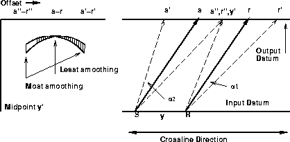
Datuming is generally formulated in separate steps for source gathers and receiver gathers, because this is most efficient. In 3-D, the large variability between inline and crossline sampling makes this a less obvious choice. Sticking to marine geometry, datuming receiver and source gathers separately inhibits energy from moving with high bandwidth in the crossline direction. Moving the operator to midpoint and offset coordinates makes it more expensive, because the operator does not separate along midpoint and offset axes the way it does along shot and receiver axes. However, in the case of poorly sampled data it can help by allowing energy to move along the crossline midpoint axis with greater bandwidth.
For each source-receiver pair at the output datum, the greatest bandwidth
is given to the input trace whose source-to-source and receiver-to-receiver
traveltime paths converge at some chosen depth in the subsurface.
Here I choose the depth to be infinite,
as shown in Figure 2.
For input midpoint y and output midpoint y', the operator has maximum bandwidth where it follows the solid rays from S to s and R to r.
The bandwidth
decreases as the angle ![]() increases.
This is not a good choice for respecting shallow reflectors and/or
long offsets; paths from the input source/receiver
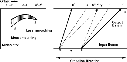
pair S and R to output pair s' and r' may be a better choice,
because (depending on velocity) they converge at finite depth in the subsurface.
The third pair, S to s'' and R to r'', only converge in the subsurface if velocity
is sufficiently complex that rays are overturned.
increases.
This is not a good choice for respecting shallow reflectors and/or
long offsets; paths from the input source/receiver
pair S and R to output pair s' and r' may be a better choice,
because (depending on velocity) they converge at finite depth in the subsurface.
The third pair, S to s'' and R to r'', only converge in the subsurface if velocity
is sufficiently complex that rays are overturned.
 |
The parallel (infinite reflector depth) traveltime paths give the shortest lag between input and output datum. This means that the least smoothing occurs at the top of the hyperbola in the output. Choosing the increasing offset traveltime paths (S to s', R to r'), or the paths which will generally converge in the subsurface, means the least smoothing occurs at a point on the hyperbola dipping towards increasing offset, which is also generally how seismic events are expected to dip (see Figure 3). Choosing the decreasing offset traveltime paths (S to s'', R to r''), means the rays only converge in the subsurface if velocity is very complex. It also means that the least smoothing on the hyperbola is where it dips to decreasing offset (and seismic events only dip towards decreasing offset in CMP gathers in the case of complex velocity).
 |
Because the operator is more efficient in frequency and space than in time, I determine a threshold frequency rather than convolve with triangles. To be unaliased, a dipping plane wave must reach adjacent surface points within a half wavelength, which yields the well-known relation
![]()