


Next: Target-oriented wavefront synthesis
Up: Wavefront synthesis using wave
Previous: Wavefront synthesis using wave
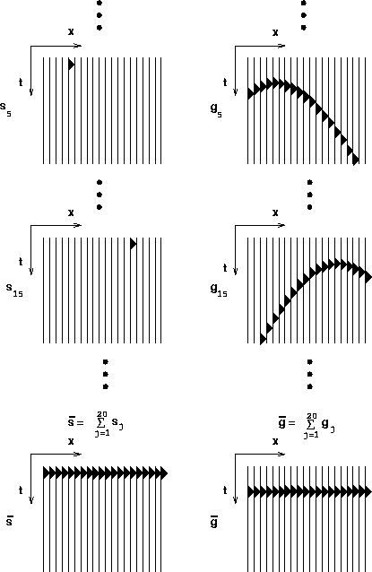
The simplest case in wavefront synthesis is synthesizing
a horizontal plane-wave source at the surface Taner (1976).
It can be done by stacking traces along a common receiver gather
and is equivalent to the wave stack equation (![[*]](http://sepwww.stanford.edu/latex2html/cross_ref_motif.gif) )
with
)
with  equal to 1 for all j.
Figure
 ![[*]](http://sepwww.stanford.edu/latex2html/cross_ref_motif.gif) shows this synthesis schematically.
shows this synthesis schematically.
Schultz and Claerbout 1978 have noted
that reflectors of different dips can be shown more clearly
by synthesizing various slanted plane waves
and used the synthesis to estimate the velocity.
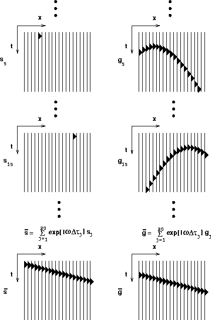
Such a slanted plane wave synthesis is obtained
by applying the wave stack equation (![[*]](http://sepwww.stanford.edu/latex2html/cross_ref_motif.gif) ) with
) with
| ![\begin{displaymath}
\gamma_j = \exp [i\omega \tau_j]\end{displaymath}](img11.gif) |
(5) |
where

In equation (![[*]](http://sepwww.stanford.edu/latex2html/cross_ref_motif.gif) ),
),  is the temporal frequency
(recall that equation (
is the temporal frequency
(recall that equation (![[*]](http://sepwww.stanford.edu/latex2html/cross_ref_motif.gif) ) is formulated
for a monochromatic field.),
) is formulated
for a monochromatic field.),
 is the time shifting of each source with respect to the reference
source and depends on p, which is the ray parameter
that controls the direction of wavefront propagation,
and
  is the interval between sources.
Figure
 ![[*]](http://sepwww.stanford.edu/latex2html/cross_ref_motif.gif) explains schematically a simple
example of the slanted wavefront synthesis.
explains schematically a simple
example of the slanted wavefront synthesis.
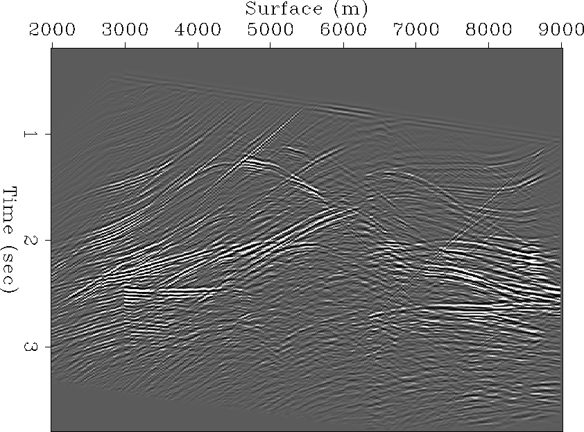
For a more realistic example, the Marmousi data set is used.
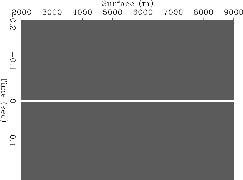
Figure ![[*]](http://sepwww.stanford.edu/latex2html/cross_ref_motif.gif) is the stacked section obtained by synthesizing
a plane wave with p = 0 s/m at the surface (Figure
is the stacked section obtained by synthesizing
a plane wave with p = 0 s/m at the surface (Figure ![[*]](http://sepwww.stanford.edu/latex2html/cross_ref_motif.gif) )
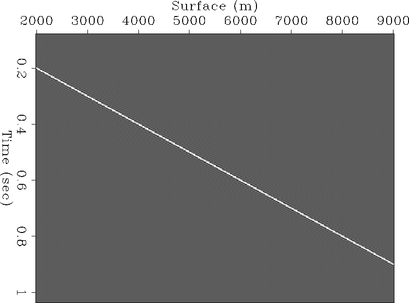
and the stacked section shown in Figure
)
and the stacked section shown in Figure ![[*]](http://sepwww.stanford.edu/latex2html/cross_ref_motif.gif) is
obtained by synthesizing a plane wave
with p = 0.0001 s/m (Figure
is
obtained by synthesizing a plane wave
with p = 0.0001 s/m (Figure ![[*]](http://sepwww.stanford.edu/latex2html/cross_ref_motif.gif) ).
The value of p (= 0.0001 s/m) was chosen so that the plane wavefront
would have a 10 degrees incidence angle to a flat reflector whose velocity
is 1700 m/s, which is the average velocity of the medium
near the bottom of the water.
In Figure
).
The value of p (= 0.0001 s/m) was chosen so that the plane wavefront
would have a 10 degrees incidence angle to a flat reflector whose velocity
is 1700 m/s, which is the average velocity of the medium
near the bottom of the water.
In Figure ![[*]](http://sepwww.stanford.edu/latex2html/cross_ref_motif.gif) we can observe that some of the dipping events
are enhanced and the water bottom reflection that is strong in
Figure
we can observe that some of the dipping events
are enhanced and the water bottom reflection that is strong in
Figure ![[*]](http://sepwww.stanford.edu/latex2html/cross_ref_motif.gif) becomes weak.
In these stacked sections, we can see that the reflectors whose
dip is normal to the direction of the wavefront propagation are
more clearly visible than the others, respectively.
becomes weak.
In these stacked sections, we can see that the reflectors whose
dip is normal to the direction of the wavefront propagation are
more clearly visible than the others, respectively.
syn-plane-0
Figure 4 A plane-wave synthesis at the surface.
 syn-plane-1
Figure 5 A slanted plane-wave synthesis at the surface.
 marm-syn-pln-0
Figure 6 Synthesis operator to synthesize a plane-wave with p = 0 (s/m) at surface.


 marm-stk-pln-0
Figure 7 Wave stacked section of Marmousi data set with synthesis operator shown in Figure ![[*]](http://sepwww.stanford.edu/latex2html/cross_ref_motif.gif) .
.


 marm-syn-pos-0
Figure 8 Synthesis operator that synthesizes a plane-wave with p = .0001 (s/m) at surface.


 marm-stk-pos-0
Figure 9 Wave-stacked section of Marmousi data set with synthesis operator shown in Figure ![[*]](http://sepwww.stanford.edu/latex2html/cross_ref_motif.gif) .
.


Next: Target-oriented wavefront synthesis
Up: Wavefront synthesis using wave
Previous: Wavefront synthesis using wave
Stanford Exploration Project
2/5/2001
![[*]](http://sepwww.stanford.edu/latex2html/cross_ref_motif.gif) )
with
)
with ![[*]](http://sepwww.stanford.edu/latex2html/cross_ref_motif.gif) shows this synthesis schematically.
shows this synthesis schematically.
![[*]](http://sepwww.stanford.edu/latex2html/cross_ref_motif.gif) )
with
)
with ![]() equal to 1 for all j.
Figure
equal to 1 for all j.
Figure ![[*]](http://sepwww.stanford.edu/latex2html/cross_ref_motif.gif) shows this synthesis schematically.
shows this synthesis schematically.
![[*]](http://sepwww.stanford.edu/latex2html/cross_ref_motif.gif) ) with
) with
![]()
![[*]](http://sepwww.stanford.edu/latex2html/cross_ref_motif.gif) ),
), ![]() is the temporal frequency
(recall that equation (
is the temporal frequency
(recall that equation (![[*]](http://sepwww.stanford.edu/latex2html/cross_ref_motif.gif) ) is formulated
for a monochromatic field.),
) is formulated
for a monochromatic field.),
![]() is the time shifting of each source with respect to the reference
source and depends on p, which is the ray parameter
that controls the direction of wavefront propagation,
and
is the time shifting of each source with respect to the reference
source and depends on p, which is the ray parameter
that controls the direction of wavefront propagation,
and ![]() is the interval between sources.
Figure
is the interval between sources.
Figure ![[*]](http://sepwww.stanford.edu/latex2html/cross_ref_motif.gif) explains schematically a simple
example of the slanted wavefront synthesis.
explains schematically a simple
example of the slanted wavefront synthesis.
![[*]](http://sepwww.stanford.edu/latex2html/cross_ref_motif.gif) is the stacked section obtained by synthesizing
a plane wave with p = 0 s/m at the surface (Figure
is the stacked section obtained by synthesizing
a plane wave with p = 0 s/m at the surface (Figure ![[*]](http://sepwww.stanford.edu/latex2html/cross_ref_motif.gif) )
and the stacked section shown in Figure
)
and the stacked section shown in Figure ![[*]](http://sepwww.stanford.edu/latex2html/cross_ref_motif.gif) is
obtained by synthesizing a plane wave
with p = 0.0001 s/m (Figure
is
obtained by synthesizing a plane wave
with p = 0.0001 s/m (Figure ![[*]](http://sepwww.stanford.edu/latex2html/cross_ref_motif.gif) ).
The value of p (= 0.0001 s/m) was chosen so that the plane wavefront
would have a 10 degrees incidence angle to a flat reflector whose velocity
is 1700 m/s, which is the average velocity of the medium
near the bottom of the water.
In Figure
).
The value of p (= 0.0001 s/m) was chosen so that the plane wavefront
would have a 10 degrees incidence angle to a flat reflector whose velocity
is 1700 m/s, which is the average velocity of the medium
near the bottom of the water.
In Figure ![[*]](http://sepwww.stanford.edu/latex2html/cross_ref_motif.gif) we can observe that some of the dipping events
are enhanced and the water bottom reflection that is strong in
Figure
we can observe that some of the dipping events
are enhanced and the water bottom reflection that is strong in
Figure ![[*]](http://sepwww.stanford.edu/latex2html/cross_ref_motif.gif) becomes weak.
In these stacked sections, we can see that the reflectors whose
dip is normal to the direction of the wavefront propagation are
more clearly visible than the others, respectively.
becomes weak.
In these stacked sections, we can see that the reflectors whose
dip is normal to the direction of the wavefront propagation are
more clearly visible than the others, respectively.

![[*]](http://sepwww.stanford.edu/latex2html/cross_ref_motif.gif) .
.
![[*]](http://sepwww.stanford.edu/latex2html/cross_ref_motif.gif) .
.