 |
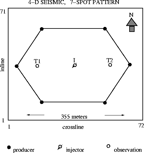
Figure 1 Duri 4-D seismic coverage over a 7-spot steamflood pattern. The steam injection well is at the center, flanked by two temperature monitor wells on either side.
Figure 1 shows a diagram of a single ``7-spot'' steam injection well pattern. The surface area of the 4-D seismic coverage is outlined by the outer box, and is 355 m on a side. The 7-spot is composed of six producing wells (black circles) connected in a hexagon, with the seventh well being the steam injector in the center (open circle with arrow). Additionally, two temperature observation wells (open circles) are located on either side of the injector.
Steam is being injected into two reservoir zones, as shown in Figure 2. Each zone is separated by thermal packers. The upper steam zone is in the P formation, which ranges from 140-200 m depth, or 155-210 ms in seismic traveltime. The lower steam zone is in the K formation, which ranges from 200-230 m in depth, or 210-245 ms in seismic traveltime.
Clay layers are suspected to cause flow barriers in the reservoirs, and heterogeneity can make steam flow directions unpredictable. For these reasons, a pilot 4-D seismic monitor experiment was conducted over this small steam injection pattern to see if vertical and lateral steam flow could be mapped from time-lapse seismic monitor data.
 |
 |