

Next: DISCUSSION
Up: REVERSE-TIME CROSSWELL DEPTH MIGRATION
Previous: Imaging horizontal reflectors
On the above smooth background velocity model, I superimposed two
dipping reflectors with depths of 40 m and 160 m at the left well.
They both tilt 15-degree upward to produce opposite dip directions
relative to the source.
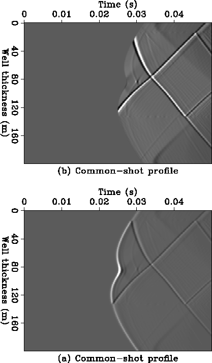
Figure 5(a) is the common-shot profile data generated
by the same recording geometry as the above horizontal reflector case.
Figure 5(b) shows data for the same common-shot profile
after the direct wave has been muted.
It is clear that the opposite dipping reflectors
generate reflection events with different amounts of moveout.
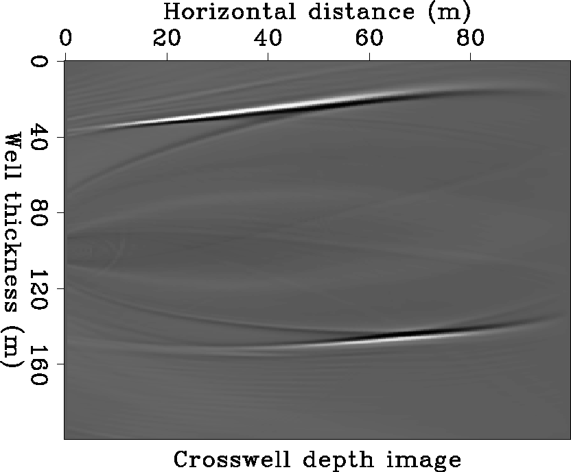
Figure 6 is the reflectivity depth image between the two wells.
All parts of the upper reflector are imaged clearly, with the exception
of a short segment near the right receiver well.
This segment is not imaged because its reflection event
is damaged by direct wave muting.
The left part of the lower reflector is not imaged.
Ray tracing indicates that its reflections do not propagate
to the receivers in the right well.
2DataH1H2
Figure 5 Crosswell
common-shot profile, (a) the data without any processing,
(b) after the direct wave has been muted. The opposite dipping reflectors
generate reflection events with different amounts of moveout.


 2Image.H
Figure 6 Crosswell depth image
generated by migrating a common-shot profile. The two dipping reflectors have
opposite dips relative to the source.
The upper reflector is imaged clearly.
The left part of the lower reflector is not imaged because its reflections
do not propagate to the receivers well.


Next: DISCUSSION
Up: REVERSE-TIME CROSSWELL DEPTH MIGRATION
Previous: Imaging horizontal reflectors
Stanford Exploration Project
11/17/1997


