![[*]](http://sepwww.stanford.edu/latex2html/cross_ref_motif.gif) .
The continuity of the slowness
across the interface (equation 3) is expressed as follows:
.
The continuity of the slowness
across the interface (equation 3) is expressed as follows:
When the medium is horizontally layered and isotropic, tracing a ray across the different interfaces is easy. From the medium velocities and the direction of the ray at the source (p), successive applications of (4) tells us how a ray changes its direction as it travels. The only angles that matter are those of the incident and refracted rays. If the layers are dipping the problem is slightly more complicated because p has the be calculated every time the ray reaches a new interface and we have to deal with three instead of two angles at each boundary.
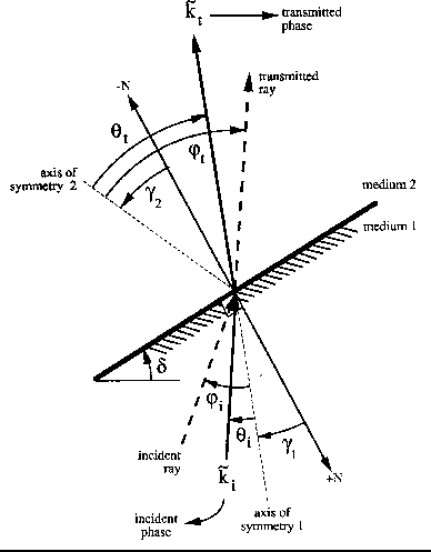
When the medium is anisotropic, we have to deal with seven angles at
each interface to figure out how a ray changes its direction. All these
angles (positive counterclockwise) are shown in Figure ![[*]](http://sepwww.stanford.edu/latex2html/cross_ref_motif.gif) .
The continuity of the slowness
across the interface (equation 3) is expressed as follows:
.
The continuity of the slowness
across the interface (equation 3) is expressed as follows:
| (5) |
Given the function ![]() for each medium, equation (5) tells us how the
incident phase
for each medium, equation (5) tells us how the
incident phase ![]() changes its direction when crossing the
interface between two media.
However, it does not say what happens to the direction
and velocity of the associated ray. These two quantities can be calculated
from the equations that relate phase and ray velocities (Byun, 1984):
changes its direction when crossing the
interface between two media.
However, it does not say what happens to the direction
and velocity of the associated ray. These two quantities can be calculated
from the equations that relate phase and ray velocities (Byun, 1984):
 |
(1) | |
| (2) | ||
| (3) |
 |
Equations (5) and (6) are the basic relations to trace a ray in a medium
where ![]() and
and ![]() are given for each layer. Byun (1984) proposes
the following procedure to do that: (1) Assign a value to
are given for each layer. Byun (1984) proposes
the following procedure to do that: (1) Assign a value to
![]() at the source position. (2) Repeat the
next steps for each layer: (a) Evaluate
at the source position. (2) Repeat the
next steps for each layer: (a) Evaluate ![]() and
and ![]() at the corresponding
at the corresponding ![]() . (b) Find
. (b) Find ![]() and
and
![]() form equation (6). (c) Trace a ray along the angle
form equation (6). (c) Trace a ray along the angle ![]() until it reaches the next interface. (d) Find p of the incident wave
using equation (5).
(e) Solve equation (5) for
until it reaches the next interface. (d) Find p of the incident wave
using equation (5).
(e) Solve equation (5) for ![]() . (3) Go to step 2-a.
. (3) Go to step 2-a.
The previous ray tracing procedure is valid for any phase velocity
function ![]() . What changes from one choice of the
velocity function to another is how
to solve step 2-e
(to find
. What changes from one choice of the
velocity function to another is how
to solve step 2-e
(to find ![]() as a function of p using equation (5)).
The next section focuses on this
step when the medium is transversely isotropic.
as a function of p using equation (5)).
The next section focuses on this
step when the medium is transversely isotropic.