

Next: INITIAL VALUE RAY TRACING
Up: Michelena: ray tracing
Previous: Introduction
A wave impinging on
a plane interface between two media must satisfy
the kinematic boundary condition
|  |
(1) |
that says that the particle velocity  must be continuos at all points on the boundary between medium 1 and medium 2
(Auld, 1990).
If the wave field is described as a superposition of functions of the
form  , the condition (1) implies that for incident
and scattered waves the component
of
  tangential to the boundary (
 )must be the same. If we divide
  by the frequency
 of the incident wave and define a vector
 of magnitude
1/v (where v is the phase velocity)
|  |
(2) |
the continuity of  implies the continuity of
 , usually called ray parameter
  :
:
|  |
(3) |
Since we know that  is parallel to the interface,
the ray parameter is usually considered as an scalar p with a positive
or negative sign in the front to indicate the sign of angle of the incident
phase with respect to the normal.
Auld (1990) examines
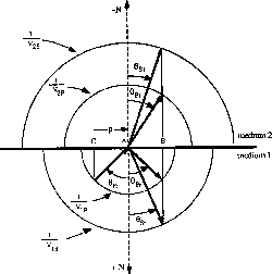
condition (3) by looking at the corresponding slowness
surfaces (a plot of  as a function of its direction), as
Figure
 ![[*]](http://sepwww.stanford.edu/latex2html/cross_ref_motif.gif) shows. In this figure the
slowness surfaces for both P and S waves are
represented for each isotropic medium. The vector
shows. In this figure the
slowness surfaces for both P and S waves are
represented for each isotropic medium. The vector  is the
projection on the interface of the point in the slowness surface that
corresponds to the incident P wave phase. From the construction
of Figure
 ![[*]](http://sepwww.stanford.edu/latex2html/cross_ref_motif.gif) it is possible to derive easily Snell's law that gives the angles of the
scattered phases for both P and S waves:
it is possible to derive easily Snell's law that gives the angles of the
scattered phases for both P and S waves:
|  |
|
| (4) |
slow-surf
Figure 1 Plane wave scattering at a plane boundary between two isotropic media. From
this construction Snell's law can be easily derived.

Snell's law tells us how a given phase changes its direction when it crosses
the interface between two media. It also tells us how rays
change direction when crossing an interface, but the medium must be
isotropic for this to be true, like in Figure ![[*]](http://sepwww.stanford.edu/latex2html/cross_ref_motif.gif) .
In isotropic media, since rays and waves
travel in the same direction
with the same velocity,
boundary conditions
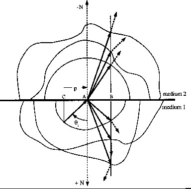
valid for waves are also used to predict the behavior of rays. In anisotropic
media, however, this simplification is no longer valid because in general
rays and waves travel with different velocities in different directions.
This is shown in Figure
.
In isotropic media, since rays and waves
travel in the same direction
with the same velocity,
boundary conditions
valid for waves are also used to predict the behavior of rays. In anisotropic
media, however, this simplification is no longer valid because in general
rays and waves travel with different velocities in different directions.
This is shown in Figure ![[*]](http://sepwww.stanford.edu/latex2html/cross_ref_motif.gif) .
.
slow-surf-ani
Figure 2 Plane wave scattering at a plane boundary between two anisotropic media.
The slowness surfaces are separated and nonspherical.
Ray directions (dashed arrows)
and phase directions (continuos arrows)
are no longer the same.(Modified from Aki and Richards, 1980.)


Next: INITIAL VALUE RAY TRACING
Up: Michelena: ray tracing
Previous: Introduction
Stanford Exploration Project
11/18/1997
![]() , the condition (1) implies that for incident
and scattered waves the component
of
, the condition (1) implies that for incident
and scattered waves the component
of ![]() tangential to the boundary (
tangential to the boundary (![]() )must be the same. If we divide
)must be the same. If we divide ![]() by the frequency
by the frequency
![]() of the incident wave and define a vector
of the incident wave and define a vector
![]() of magnitude
1/v (where v is the phase velocity)
of magnitude
1/v (where v is the phase velocity)
![]() as a function of its direction), as
Figure
as a function of its direction), as
Figure ![[*]](http://sepwww.stanford.edu/latex2html/cross_ref_motif.gif) shows. In this figure the
slowness surfaces for both P and S waves are
represented for each isotropic medium. The vector
shows. In this figure the
slowness surfaces for both P and S waves are
represented for each isotropic medium. The vector ![]() is the
projection on the interface of the point in the slowness surface that
corresponds to the incident P wave phase. From the construction
of Figure
is the
projection on the interface of the point in the slowness surface that
corresponds to the incident P wave phase. From the construction
of Figure ![[*]](http://sepwww.stanford.edu/latex2html/cross_ref_motif.gif) it is possible to derive easily Snell's law that gives the angles of the
scattered phases for both P and S waves:
it is possible to derive easily Snell's law that gives the angles of the
scattered phases for both P and S waves:


![[*]](http://sepwww.stanford.edu/latex2html/cross_ref_motif.gif) .
In isotropic media, since rays and waves
travel in the same direction
with the same velocity,
boundary conditions
valid for waves are also used to predict the behavior of rays. In anisotropic
media, however, this simplification is no longer valid because in general
rays and waves travel with different velocities in different directions.
This is shown in Figure
.
In isotropic media, since rays and waves
travel in the same direction
with the same velocity,
boundary conditions
valid for waves are also used to predict the behavior of rays. In anisotropic
media, however, this simplification is no longer valid because in general
rays and waves travel with different velocities in different directions.
This is shown in Figure ![[*]](http://sepwww.stanford.edu/latex2html/cross_ref_motif.gif) .
.
