


Next: Propagation of elastic waves
Up: Nichols: Simple anisotropic modeling
Previous: Introduction
Two way phase shift modeling is a step-by-step approach to calculating the
recorded particle velocities. The input to the process is a layered medium
and a traction applied at the surface.
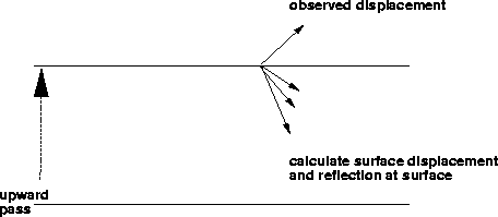
The sequence of steps in the modeling algorithm is shown in figures ![[*]](http://sepwww.stanford.edu/latex2html/cross_ref_motif.gif) to
to ![[*]](http://sepwww.stanford.edu/latex2html/cross_ref_motif.gif) .
.
pict1
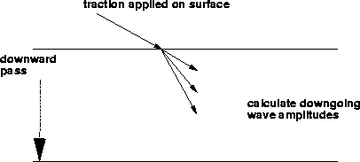
Figure 1 The first step is to calculate the (complex) amplitudes
of the three downgoing waves and the particle velocities generated by
the traction. Each phase shift uses the vertical slowness appropriate
for the wavetype.


 pict2
pict2
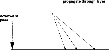
Figure 2 The second step propagates the waves to the bottom of the layer. Each component of the downgoing wavefield is phase shifted using the
Appropriate vertical slowness.


 pict3
pict3
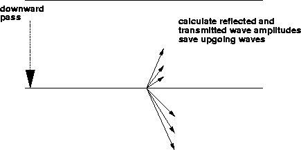
Figure 3 The third step calculates the transmitted downgoing wave amplitudes
and the reflected upgoing wave amplitudes. The upgoing amplitudes are saved
to be used later. Steps 2 and 3 are repeated until the bottom of the
model is reached.


 pict4
pict4
Figure 4 The fourth step propagates the upgoing waves in the last layer to the
top of that layer.


 pict5
pict5
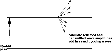
Figure 5 The fifth step calculates downgoing reflected
wave amplitudes and upgoing transmitted wave amplitudes at the top of
a layer. The upgoing reflected amplitudes at this interface that were
saved is step 3 are added into the upgoing wavefield. The downgoing
reflected amplitudes are saved to be used later. Steps 4 and 5 are
repeated until the wavefield reaches the surface.


 pict6
pict6
Figure 6 At the surface the reflected downgoing
wavefield and the particle velocities at the free surface are
calculated. The velocities are summed into the output particle
velocity field. If multiples are to be modeled the downgoing wave
field is used as the input to step 2. As the wavefield is propagated
downwards the saved downgoing reflected amplitudes saved at each
interface are added into the wavefield. Each pass down and up through
the stack of layers adds one more set of multiples to the output
displacement field.


The main loop of the program runs over the two horizontal slownesses
px and py. For each (px,py) pair I calculate the amplitude
of the recorded particle velocities at each frequency. The operators
related to free surface and boundary effects are frequency independent
as is the vertical slowness pz. The only place that the frequency
enters into the calculation is in the phase shift through each layer.
The vertical wavenumber is given by  . The frequency
independence makes the process relatively cheap. The most expensive
step is the calculation of the vertical slownesses and operators for
each layer. This calculation is only performed once for all
frequencies and for all orders of multiples. The application of the
operators and the phase shifts is fully vectorized over frequency. I
will now discuss each stage of the calculation. Most of the
mathematical detail is in the appendix.


Next: Propagation of elastic waves
Up: Nichols: Simple anisotropic modeling
Previous: Introduction
Stanford Exploration Project
12/18/1997
![[*]](http://sepwww.stanford.edu/latex2html/cross_ref_motif.gif) to
to ![[*]](http://sepwww.stanford.edu/latex2html/cross_ref_motif.gif) .
.
![[*]](http://sepwww.stanford.edu/latex2html/cross_ref_motif.gif) to
to ![[*]](http://sepwww.stanford.edu/latex2html/cross_ref_motif.gif) .
.

![]() . The frequency
independence makes the process relatively cheap. The most expensive
step is the calculation of the vertical slownesses and operators for
each layer. This calculation is only performed once for all
frequencies and for all orders of multiples. The application of the
operators and the phase shifts is fully vectorized over frequency. I
will now discuss each stage of the calculation. Most of the
mathematical detail is in the appendix.
. The frequency
independence makes the process relatively cheap. The most expensive
step is the calculation of the vertical slownesses and operators for
each layer. This calculation is only performed once for all
frequencies and for all orders of multiples. The application of the
operators and the phase shifts is fully vectorized over frequency. I
will now discuss each stage of the calculation. Most of the
mathematical detail is in the appendix.