Next: Anisotropic migration velocity analysis
Up: Residual moveout in anisotropic
Previous: RMO analysis in ADCIGs
The accuracy of the RMO function predicted from
equations 5 to 7 is demonstrated in
Biondi (2005a,b), for a large
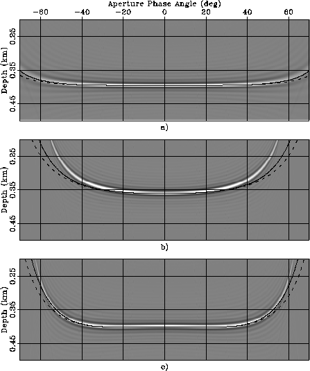
range of velocity perturbations. Figure ![[*]](http://sepwww.stanford.edu/latex2html/cross_ref_motif.gif) presents the
ADCIGs obtained when a flat reflector is migrated with inaccurate
migration velocity models. The data were modeled using the anisotropic
parameters of the Taylor Sand Tsvankin (2001):
presents the
ADCIGs obtained when a flat reflector is migrated with inaccurate
migration velocity models. The data were modeled using the anisotropic
parameters of the Taylor Sand Tsvankin (2001):  and
and
 . It was then migrated using: a) a velocity uniformly
perturbed by
. It was then migrated using: a) a velocity uniformly
perturbed by  , b) a velocity uniformly perturbed by
 , and c) an isotropic velocity with the correct vertical
velocity. The predicted residual moveouts derived
from equations 5 to 7 are
superimposed. The solid line was computed when
, and c) an isotropic velocity with the correct vertical
velocity. The predicted residual moveouts derived
from equations 5 to 7 are
superimposed. The solid line was computed when  was
derived from
was
derived from  by applying
equation 11, whereas the dashed line was computed using
the approximation
by applying
equation 11, whereas the dashed line was computed using
the approximation  .
.
The predicted RMO functions accurately track the actual RMO
functions when the perturbations are sufficiently small to
be within the linearization accuracy range
(Figure -a).
Even when the perturbations are large (Figures -b
and -c) and cause a substantial RMO,
the predicted RMO functions are excellent approximations of the true
RMO functions. In contrast, the approximation of
the group angles with the phase angles (dashed lines in the figures)
seriously lowers the accuracy of the predicted RMO functions.
Aniso-rmo
Figure 2 ADCIG obtained when data modeled using constant
anisotropic parameters (Taylor Sand) have been migrated using:
a) a velocity uniformly
perturbed by , b) a velocity uniformly perturbed by
, and c) an isotropic velocity with the correct
vertical velocity. Superimposed onto the images are the RMO functions
computed using equations 5 to
7. The solid line was computed when was
derived from by applying
equation 11, whereas the dashed line was
computed with the approximation .


Next: Anisotropic migration velocity analysis
Up: Residual moveout in anisotropic
Previous: RMO analysis in ADCIGs
Stanford Exploration Project
5/6/2007