

Next: Analysis of ADCIGs and
Up: Anisotropic migration velocity analysis
Previous: Description of the available
We restricted ourselves to 2D anisotropic migration velocity
estimation and to mild dips. For that reason, we selected a line where
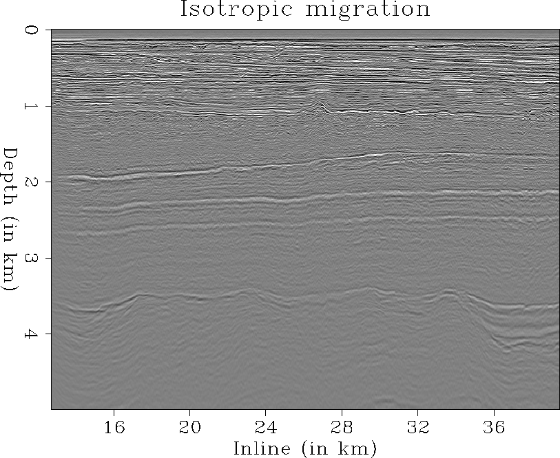
crossline and inline dips are limited (Line 750 illustrated
in Figure ![[*]](http://sepwww.stanford.edu/latex2html/cross_ref_motif.gif) ). As illustrated, the geologic
structure along line 750 is relatively flat, and the assumption
of flat reflectors is reasonable. This allows us to use the analytical
expression of the RMO in ADCIGs presented by
Biondi (2005b) and to compute anisotropic velocity
spectra. Furthermore, it has the advantage of having a nearby
well. This gives us useful vertical velocity constraints when building
the anisotropic velocity model.
). As illustrated, the geologic
structure along line 750 is relatively flat, and the assumption
of flat reflectors is reasonable. This allows us to use the analytical
expression of the RMO in ADCIGs presented by
Biondi (2005b) and to compute anisotropic velocity
spectra. Furthermore, it has the advantage of having a nearby
well. This gives us useful vertical velocity constraints when building
the anisotropic velocity model.
In our estimation procedure, we use an anisotropic
source-receiver migration program and first perform an isotropic
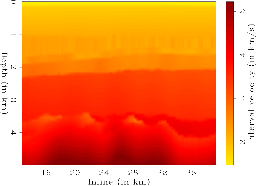
migration of the data starting from the interval vertical velocity
model developed by CGG (Figure ![[*]](http://sepwww.stanford.edu/latex2html/cross_ref_motif.gif) ). The migration
result is illustrated in the Figure
). The migration
result is illustrated in the Figure ![[*]](http://sepwww.stanford.edu/latex2html/cross_ref_motif.gif) .
.
Section-iso-750
Figure 10
Line 750: Migration result obtained after isotropic source-receiver
migration.


Velocity-750
Figure 11
Line 750: Starting isotropic interval velocity model obtained by CGG
(2003).


Next: Analysis of ADCIGs and
Up: Anisotropic migration velocity analysis
Previous: Description of the available
Stanford Exploration Project
5/6/2007
![[*]](http://sepwww.stanford.edu/latex2html/cross_ref_motif.gif) ). As illustrated, the geologic
structure along line 750 is relatively flat, and the assumption
of flat reflectors is reasonable. This allows us to use the analytical
expression of the RMO in ADCIGs presented by
Biondi (2005b) and to compute anisotropic velocity
spectra. Furthermore, it has the advantage of having a nearby
well. This gives us useful vertical velocity constraints when building
the anisotropic velocity model.
). As illustrated, the geologic
structure along line 750 is relatively flat, and the assumption
of flat reflectors is reasonable. This allows us to use the analytical
expression of the RMO in ADCIGs presented by
Biondi (2005b) and to compute anisotropic velocity
spectra. Furthermore, it has the advantage of having a nearby
well. This gives us useful vertical velocity constraints when building
the anisotropic velocity model.

