


Next: Plane-wave source migration
Up: Shan et al.: Plane-wave
Previous: Introduction
The original surface seismic data are usually shot gathers. A typical seismic shot gather
(the receiver wavefield of a shot at the surface) is
a five dimensional object: R(sy,sx,ry,rx,z=0,t),
where (sy,sx) is the source location,
(rx,ry) is the receiver location and t is the travel time.
After a Fourier transformation in t, we have the receiver wavefield in the frequency
domain 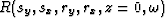 , where
  is the angular frequency.
Each shot represents a real physical experiment.
The most straight forward way to obtain the image of the subsurface
is shot-profile migration, in which we obtain
the local image of each experiment independently and form the final image
of the subsurface by stacking all the local images.
A typical shot-profile migration algorithm includes two steps. First, source and receiver wavefields
are extrapolated into the subsurface using one-way wave equations. In isotropic media they are defined as follows:
| 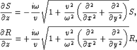 |
(1) |
| (2) |
where v=v(x,y,z) is the velocity of the media,  is the source wavefield,
which is an impulse at the surface and
is the source wavefield,
which is an impulse at the surface and  is the receiver wavefield.
Second, the image is formed by cross-correlating
the source and receiver wavefields:
is the receiver wavefield.
Second, the image is formed by cross-correlating
the source and receiver wavefields:
|  |
(3) |