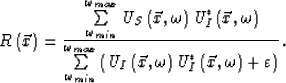
next up previous print clean
Next: (2) Wave theory tomography Up: (A) Non-iterative linearized migration/inversion Previous: (A) Non-iterative linearized migration/inversion

(1) Wave equation prestack migration/inversion

Near the scattering point $\vec{x}$, we can define an error function or a norm as  
 \begin{displaymath}
\textit{E}\left(R\left( \vec{x}\right) \right)=\sum_{\omega_...
 ...{x}, \omega \right)R\left( \vec{x}\right)\right) ^{2} d\omega ,\end{displaymath} (34)
where $R\left(\vec{x}\right) $ is the reflectivity, $\textit{U}_{S}\left(\vec{x}, \omega \right)$ is the upcoming wavefield, which is downward extrapolated to a reflector, and $\textit{U}_{I}\left(\vec{x}, \omega \right)$ is the incident wavefield propagated to the reflector. At the scattering point $\vec{x}$ , the scattering wavefield $\textit{U}_{S}\left(\vec{x}, \omega \right)$ should be equal or close to the convolution between the incident wavefield $\textit{U}_{I}\left(\vec{x}, \omega \right)$ and the reflectivity function. From equation (34), the imaging condition of the migration/inversion is as follows:  
 \begin{displaymath}
R\left( \vec{x}\right)=\frac{\sum\limits_{\omega_{min}}^{\om...
 ...{U}_{I}^{*}\left(\vec{x}, \omega \right)+\varepsilon \right) }.\end{displaymath} (35)
The term in the numerator is a correlation imaging for prestack migration. The term in the denominator expresses the illumination of the scattering points. Fig.2 geometrically explains the imaging condition, which says that the imaging occurs at the arrival time of the incident wave which equals the take-off time of the upcoming wave.

 
Imaging_fig
Figure 2
The geometry explication of the cross-correlation imaging condition. S* is a virtual source of the real source S. The propagator L* is the conjugate of the downward propagator L. Therefore, both the propagator LH and L* collapse the wavefronts into a point--the imaging point P.
Imaging_fig
view burn build edit restore

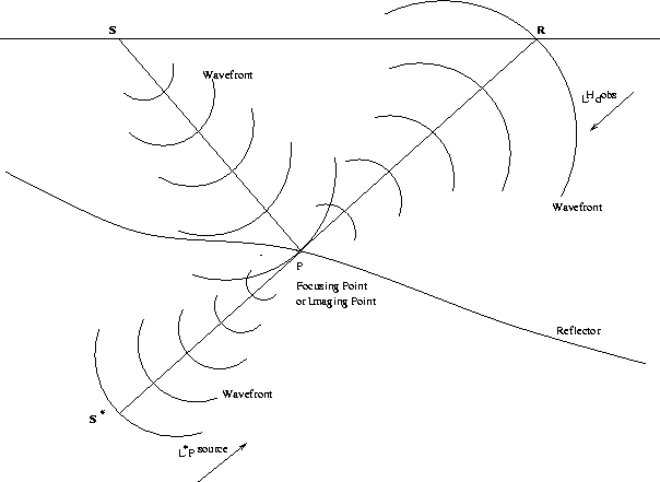
In the frequency domain, the extrapolated upcoming wavefield at the scattering point is  
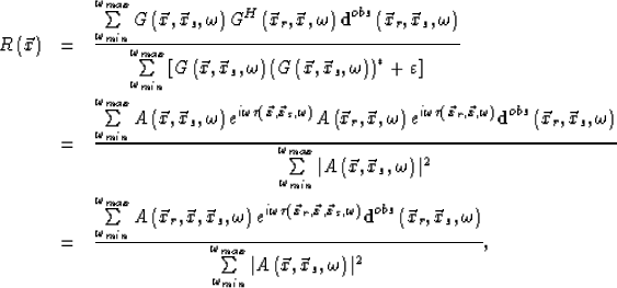
 \begin{displaymath}
\textit{U}_{S}\left( \vec{x}, \omega \right)= G^{H}\left(\ve...
 ...\textbf{d}^{obs}\left( \vec{x}_{r},\vec{x}_{s}, \omega\right) ,\end{displaymath} (36)
and the incident wavefield at the same point is  
 \begin{displaymath}
\textit{U}_{I}\left( \vec{x}, \omega \right)=G\left(\vec{x},\vec{x}_{s}, \omega \right) .\end{displaymath} (37)
Substituting equations (36) and (37) into equation (35) and applying the WKBJ approximation to the Green's functions, we can rewrite equation (35) as follows:
   \begin{eqnarray}
R\left( \vec{x}\right)&=&\frac{\sum\limits_{\omega_{min}}^{\ome...
 ...max}}\vert A\left(\vec{x},\vec{x}_{s}, \omega \right) \vert^{2} },\end{eqnarray}
(38)
where $A\left(\vec{x}_{r},\vec{x}, \vec{x}_{s}, \omega \right)=A\left(\vec{x},\vec{x}_{s}, \omega \right)A\left(\vec{x}_{r},\vec{x}, \omega \right)$ and $\tau \left(\vec{x}_{r}, \vec{x},\vec{x}_{s}, \omega \right)=\tau \left(\vec{x},\vec{x}_{s}, \omega \right)+\tau \left(\vec{x}_{r},\vec{x}, \omega \right) $.From equation (38), it is clear that the seismic illumination plays a key role in migration/inversion imaging. The possibility of relative true-amplitude imaging will be discussed later.


next up previous print clean
Next: (2) Wave theory tomography Up: (A) Non-iterative linearized migration/inversion Previous: (A) Non-iterative linearized migration/inversion
Stanford Exploration Project
11/1/2005