


|
zsoff_mig_all
Figure 8 Zero subsurface-offset section extracted from the image obtained by migrating the data with a two constant-velocity layer model: 1500 m/s above the reflector and 2800 m/s below the reflector. | 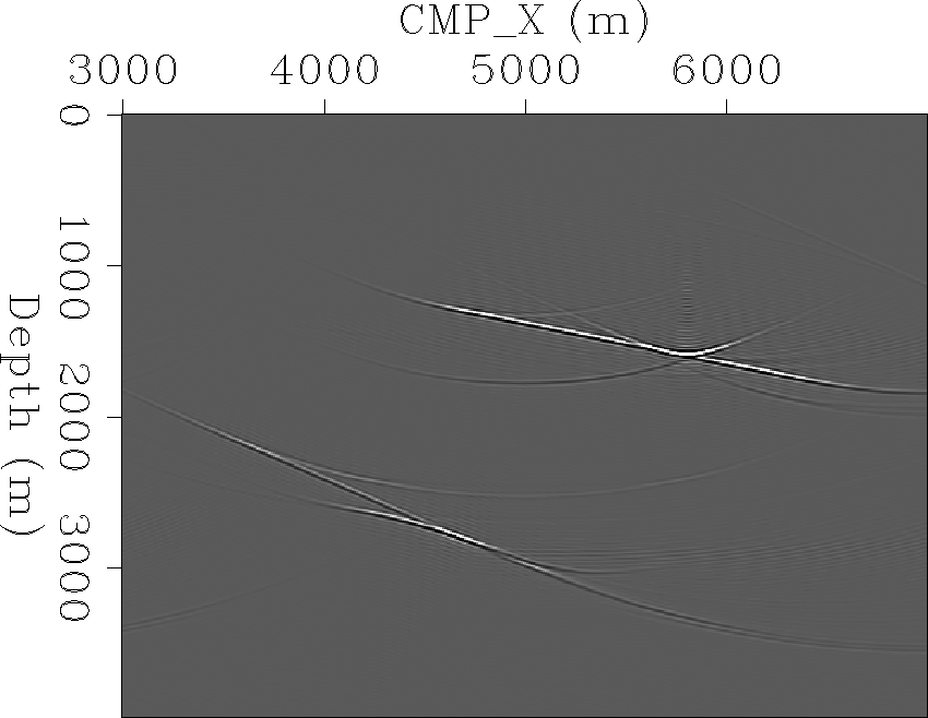 |


 |
|
zsoff_mig_all_const
Figure 10 Zero subsurface-offset section extracted from the image obtained by migrating the data with constant water velocity. |  |
Figure ![[*]](http://sepwww.stanford.edu/latex2html/cross_ref_motif.gif) shows the zero subsurface offset section extracted
form the image data migrated with a velocity model that consists of two constant
velocity layers:
1500 m/s above the reflector and 2800 m/s below the reflector. Two reference
velocities were used for the migration at each depth step. As expected, the
water-bottom (primary) reflector and the diffraction
are properly imaged since they were migrated with a velocity close to the true velocity.
The water-bottom multiple and the diffracted multiple,
on the other hand, have both been migrated. This can be seen more clearly in
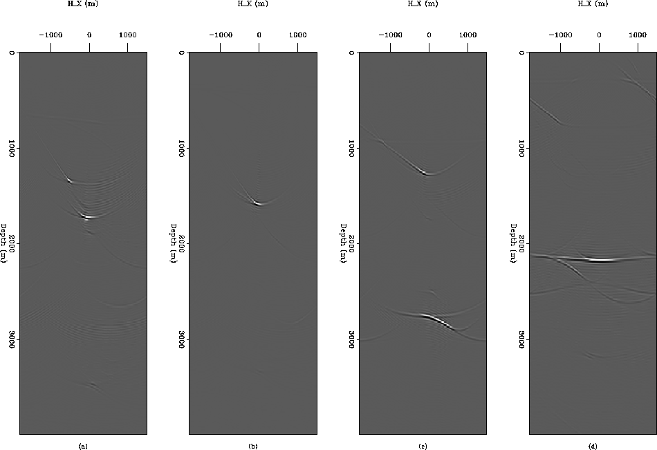
Figure , which shows four subsurface-offset common image gathers
at four different horizontal locations: (a) CMP_X=6280 m, a primary location;
(b) CMP_X=5800 m, diffractor location; (c) CMP_X=4600 m, a diffracted multiple
location; and (d) CMP_X=3600 m, a water-bottom multiple location. The primary and
the diffraction are well focused at zero subsurface offset, but not the multiples,
since they were migrated with the wrong velocity.
shows the zero subsurface offset section extracted
form the image data migrated with a velocity model that consists of two constant
velocity layers:
1500 m/s above the reflector and 2800 m/s below the reflector. Two reference
velocities were used for the migration at each depth step. As expected, the
water-bottom (primary) reflector and the diffraction
are properly imaged since they were migrated with a velocity close to the true velocity.
The water-bottom multiple and the diffracted multiple,
on the other hand, have both been migrated. This can be seen more clearly in
Figure , which shows four subsurface-offset common image gathers
at four different horizontal locations: (a) CMP_X=6280 m, a primary location;
(b) CMP_X=5800 m, diffractor location; (c) CMP_X=4600 m, a diffracted multiple
location; and (d) CMP_X=3600 m, a water-bottom multiple location. The primary and
the diffraction are well focused at zero subsurface offset, but not the multiples,
since they were migrated with the wrong velocity.
There is, however, an important difference
between the image of the water-bottom multiple and that of the diffracted multiple.
This can be seen in Figure that shows the
zero-subsurface offset section but for the image obtained by migrating thye data with
constant water velocity (1500 m/s). The primary and the diffractor are both perfectly
imaged since they were migrated with the exact velocity. The water-bottom multiple
is also imaged perfectly as a primary
with twice the dip of the real primary. The diffracted multiple, on the other hand,
is still poorly imaged and does not show as a diffractor at all, since its kinematics
do not match those of a primary
reflection as explained before. Figure shows the same
image gathers as those in Figure . Notice the good focusing
of the water-bottom multiple.
 |
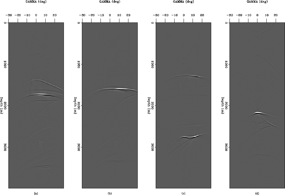
Since the ``natural'' prestack domain of data migrated with wave-equation migration
for velocity analysis is the aperture angle rather than the subsurface offset, it is
worth looking at the results of the migration in this domain.
Figure shows angle-domain common-image gathers extracted from
the image obtained by migrating the data with the two-velocity layer model at the same
spatial locations as in Figure . The primary shows a good
coverage of aperture angles. The diffraction samples even more aperture angles,
since it is not restricted by Snell's law whereas the water-bottom multiple shows
the characteristic overmigration. The diffracted multiple shows the expected,
complicated apex-shifted moveout.
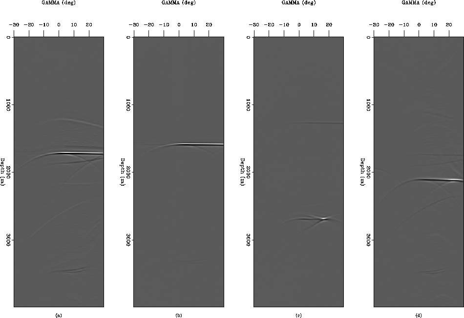
Finally, Figure shows the angle-domain
common-image gathers at the same spatial locations as in Figure
but corresponding to the data migrated with constant velocity. Notice how the moveout
of then water-bottom multiple is flat like that of the primary but its range of aperture
angles is much smaller as is intuitively obvious. The diffracted multiple shows
focusing at its apex, located at an aperture angle of about 15 degrees.
 |
 |