| |
(8) |
 |
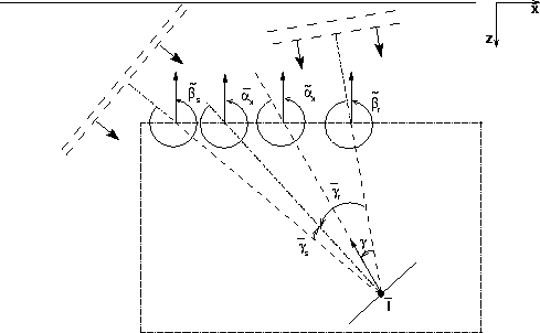
Figure ![[*]](http://sepwww.stanford.edu/latex2html/cross_ref_motif.gif) shows the geometric
interpretation of these angles.
Notice that the average dip angle
shows the geometric
interpretation of these angles.
Notice that the average dip angle
![]() is different from the
true geological dip angle
is different from the
true geological dip angle ![]() ,and that the average aperture angle
,and that the average aperture angle ![]() is
obviously different from the true
aperture angles
is
obviously different from the true
aperture angles ![]() and
and ![]() .However, the five angles are related
and, if needed, the true angles can be derived
from the average angles
Rosales and Biondi (2005).
.However, the five angles are related
and, if needed, the true angles can be derived
from the average angles
Rosales and Biondi (2005).
The transformation to the angle domain transforms
the prestack image from the migrated subsurface offset domain ![]() ,to the angle domain by a slant stack transform.
The transformation axis is thus the physical dip
of the image along the subsurface offset;
that is,
,to the angle domain by a slant stack transform.
The transformation axis is thus the physical dip
of the image along the subsurface offset;
that is,
![]() .The dip angles can be similarly related to the midpoint dips
in the image;
that is,
.The dip angles can be similarly related to the midpoint dips
in the image;
that is,
![]() .Following
the derivation of acoustic isotropic ADCIGs
by Sava and Fomel (2003)
and of converted-waves ADCIGs by
Rosales and Rickett (2001),
we can write the following relationships between
the propagation angles and the derivative
measured from the wavefield:
.Following
the derivation of acoustic isotropic ADCIGs
by Sava and Fomel (2003)
and of converted-waves ADCIGs by
Rosales and Rickett (2001),
we can write the following relationships between
the propagation angles and the derivative
measured from the wavefield:
 |
(9) | |
| (10) | ||
| (11) |
 |
(12) | |
| (13) |
Solving for ![]() and
and ![]() we obtain the following:
we obtain the following:
 |
(14) | |
| (15) |
Substituting equation 15 in equation 14, and equation 14 into equation 15, we get the following two quadratic expressions that can be solved to estimate the angles as a function of the dips measured from the image:
 |
(16) | |
| (17) |
For anisotropic velocities, the slownesses depend on the propagation
angles, and thus the normalized difference depends on
the unknown ![]() and
and ![]() .In practice, these equations can be solved by
a simple iterative process that starts by
assuming the ``normalized difference'' to be equal to zero.
In all numerical test I conducted
this iterative process converges to the correct solution in
only a few iterations, and thus is not computationally demanding.
.In practice, these equations can be solved by
a simple iterative process that starts by
assuming the ``normalized difference'' to be equal to zero.
In all numerical test I conducted
this iterative process converges to the correct solution in
only a few iterations, and thus is not computationally demanding.
The dependency of equations 16 and 17 from the slowness function is also an impediment to the use of efficient Fourier-domain methods to perform the transformation to angle domain, because the slowness function cannot be assumed to be constant. Fortunately, the numerical examples shown below indicate that for practical values of the anisotropy parameters the dependency of the estimate from the dip angles can be safely ignored for small dips, and it is unlikely to constitute a problem for steep dips.