

Next: Examples
Up: Shan and Biondi: Tilted
Previous: Tilted Cartesian coordinates
In shot-profile migration, offset-domain CIGs can be obtained
by cross-correlating the source and receiver wavefields with a horizontal shift Rickett and Sava (2002).
The offset-domain CIGs can be transformed into ADCIGs
by slant-stack Sava and Fomel (2003). In reverse-time migration,
in addition to horizontal offset-domain CIGs, we have vertical offset-domain CIGs, which
are obtained by cross-correlating the source and receiver wavefields with a vertical shift
Biondi and Shan (2002). Both horizontal and vertical offset-domain CIGs can be transformed
into ADCIGs and merged into dip-dependent CIGs, by transforming the horizontal
and vertical offsets into apparent geological offset as follows Biondi and Symes (2003):
|  |
(2) |
| (3) |
where  is the dip angle of the subsurface reflector, hx is the horizontal offset, hz is the
vertical offset and h0 is the apparent geological offset.
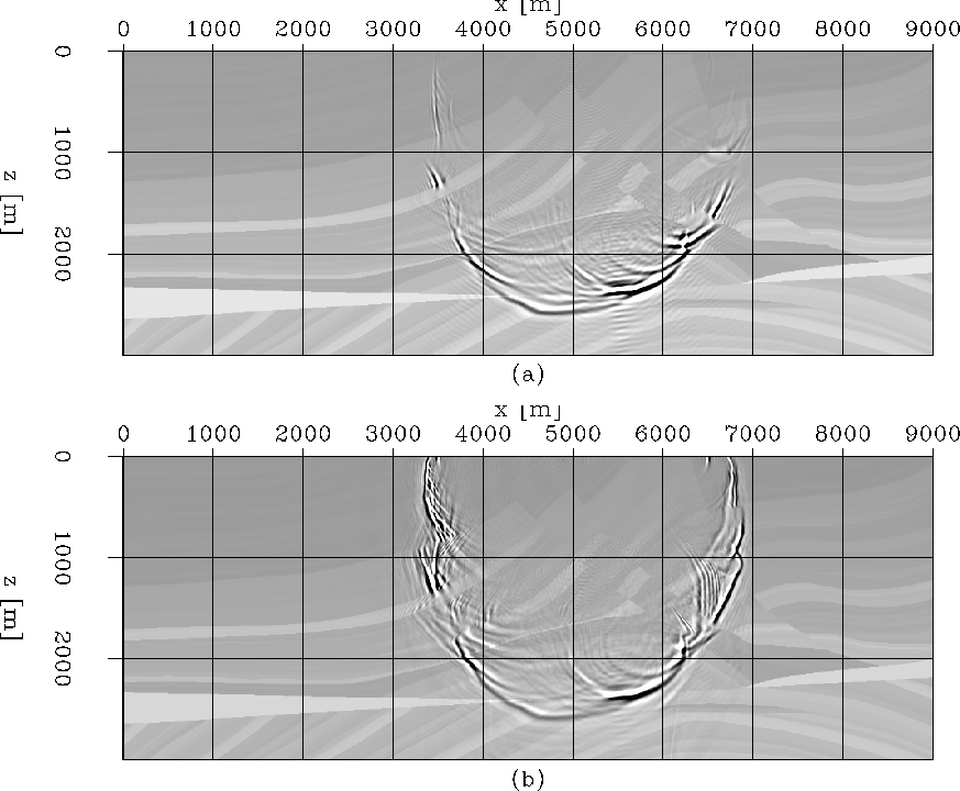
mar.green
Figure 2 The Marmousi model: (a) wavefields
obtained by downward continuation with FFD; (b) wavefields obtained by plane-wave decomposition and
extrapolation in tilted coordinates.

In the tilted coordinates, wavefields are extrapolated in the  direction. The
offset-domain CIGs are generated by cross-correlating the source and receiver wavefields with
an
  direction shift. So the subsurface offset is in the
  direction.
As with the apparent geological offset h0, the
  direction offset
  can be transformed to horizontal and vertical offsets as follows:
|  |
(4) |
| (5) |
where  is the tilting angle in Figure 1.
As for reverse-time migration, horizontal and vertical offset-domain CIGs can be transformed
into ADCIGs and merged into dip-dependent ADCIGs. A simple way to merge them is with the following weights:
|  |
(6) |
| (7) |
where  is the apparent dip angle of the reflector. Dip-dependent residual
moveout Shan and Biondi (2003) can be used to analyze dip-dependent ADCIGs to provide
useful moveout information for velocity analysis.
In tilted coordinates, the direction of subsurface offset is close to that of apparent geological offset,
since the extrapolation direction of the wavefields is close to the propagation direction of the
waves. Within a limited length of subsurface offsets, we can obtain much more accurate CIGs at steeply
dipping reflectors than with standard downward continuation.


Next: Examples
Up: Shan and Biondi: Tilted
Previous: Tilted Cartesian coordinates
Stanford Exploration Project
5/23/2004


![]() direction. The
offset-domain CIGs are generated by cross-correlating the source and receiver wavefields with
an
direction. The
offset-domain CIGs are generated by cross-correlating the source and receiver wavefields with
an ![]() direction shift. So the subsurface offset is in the
direction shift. So the subsurface offset is in the ![]() direction.
As with the apparent geological offset h0, the
direction.
As with the apparent geological offset h0, the ![]() direction offset
direction offset ![]() can be transformed to horizontal and vertical offsets as follows:
can be transformed to horizontal and vertical offsets as follows:
