 |
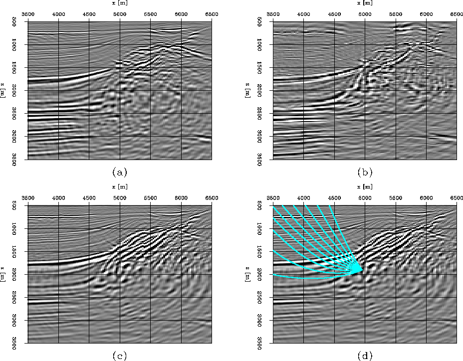
Figure 3 Migration of North Sea real dataset: (a) the image from downward continuation; (b) the image from reverse-time migration; (c) the image from plane-wave migration in tilted coordinates; (d) the rays shot at x=5000m, z=1900m.
 |
Our second example images the overturned waves of a 2-D line from the ELF L7D North Sea dataset. This dataset presents challenges caused by the interaction between the salt edge and a chalk layer. The migration velocity is a smooth version of a tomographic result, which was obtained by inverting the moveouts measured on ADCIGs computed from downward-continuation prestack migration Clapp (2001). The image from reverse-time migration Biondi and Shan (2002) shows the presence of overturned energy. Figure 3 shows (a) the image obtained by downward continuation, (b) the image obtained by reverse-time migration, (c) the image obtained by plane-wave migration in tilted coordinates and (d) the rays shot from the steeply dipping reflector. Note that, to save computational cost, we use large space-sampling in reverser-time migration, which make reflectors in Figure 3b not as continuous as the others. There are two steeply dipping reflectors at the edge of the salt, one of which is almost vertical. Rays from these two reflectors (Figure 3d) show that the waves are overturned. Downward continuation (Figure 3a) doesn't image these two steeply dipping reflectors, failing to handle the overturned energy. In contrast, both reverse-time prestack migration (Figure 3b) and plane-wave migration in tilted coordinates (Figure 3c) preserve the overturned energy and image the steeply dipping reflectors. The images of the steep reflectors by these two methods are comparable, but the cost of plane-wave migration in tilted coordinates is much less than that of reverse-time migration.
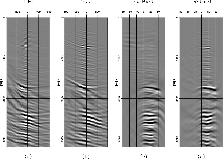
Figure 4 compares the horizontal CIGs at the surface location x=4000m from plane-wave migration in tilted coordinates with those from reverse-time migration. Figure 4a and Figure 4c show offset and angle domain CIGs from reverse-time migration, respectively. Figure 4b and Figure 4d show offset and angle domain CIGs from plane-wave migration in tilted coordinates, respectively. The ADCIGs from plane-wave migration in tilted coordinates look similar to those from reverse-time migration.
 |
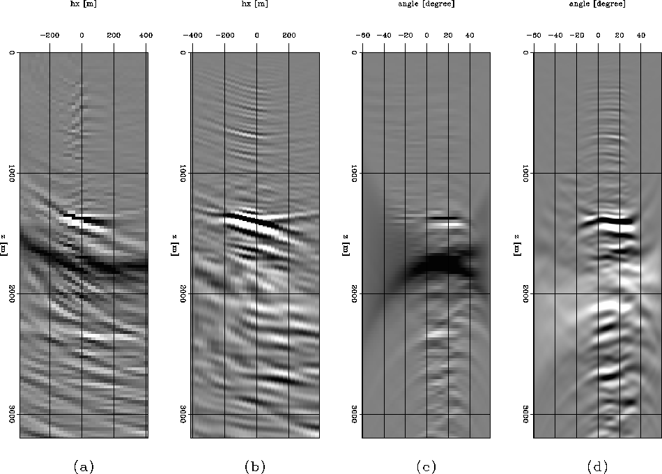
Figure 5 compares the horizontal CIGs at the surface location x=5000m from plane-wave migration in tilted coordinates with those from reverse-time migration. Panels are organized as in Figure 4. The vertical salt edge is located at surface location x=5000m, in the vertical interval 1500<z<2000m. At the vertical salt edge, we show that the ADCIGs from reverse-time migration and from plane-wave migration in tilted coordinates are similarly smeared along the angle axis. This smearing noise makes horizontal CIGs a poor source of information for velocity analysis at these steeply dipping reflectors.
 |
Figure 6 compares the vertical CIGs at depth z=1900m from plane-wave migration in tilted coordinates with those from reverse-time migration. Panels are organized as in Figure 4 but in the vertical direction. The vertical ADCIGs from both methods are similar. In contrast to horizontal CIGs, vertical CIGs focus at the vertical salt edge and can provide useful information for velocity analysis at the salt edge.
Figure 7 shows the dip-dependent ADCIGs obtained by merging horizontal and vertical ADCIGs with the weights in equations (6) and (7). Comparing against horizontal and vertical ADCIGs, we find that dip-dependent ADCIGs are more robust. The smearing noise is avoided and both horizontal and vertical reflectors are well focused.