

Next: Smoothing and damping, accuracy
Up: Data examples
Previous: Marine 3-D shot interpolation
For some applications, it may make sense to refine the crossline
receiver sampling.
Prestack datuming, for instance,
can be hampered in 3-D because the relatively sparse crossline
sampling requires much stronger antialiasing on energy moving in
the crossline direction than on energy moving in the inline direction.
The SRME demultiple method requires many more receivers than are
recorded, in order to model multiples that bounce at surface locations
between streamers.
In both cases, there are other issues as well.
In particular, sources tend to be placed nearly at the center of
the crossline range of the receiver spread, and should be extrapolated
outward in the crossline direction, for reciprocity's sake.
That should probably be done with some other algorithm, because
the very narrow dip range that should exist between the two
nearly central, only slightly separated sources is not likely to
have information necessary to model sources far away.
Put another way, PEFs can always interpolate, but can only extrapolate
along straight lines.
In the 3-D field data example above, there are only three streamers,
with a narrow aperture,
so it does not seem especially interesting to interpolate between them.
Energy moving in the crossline direction probably becomes more important
when there is a larger crossline aperture, as is the case with newer
seismic acquisition boats which may tow a dozen or more cables.
Unfortunately, no data from those boats was available.
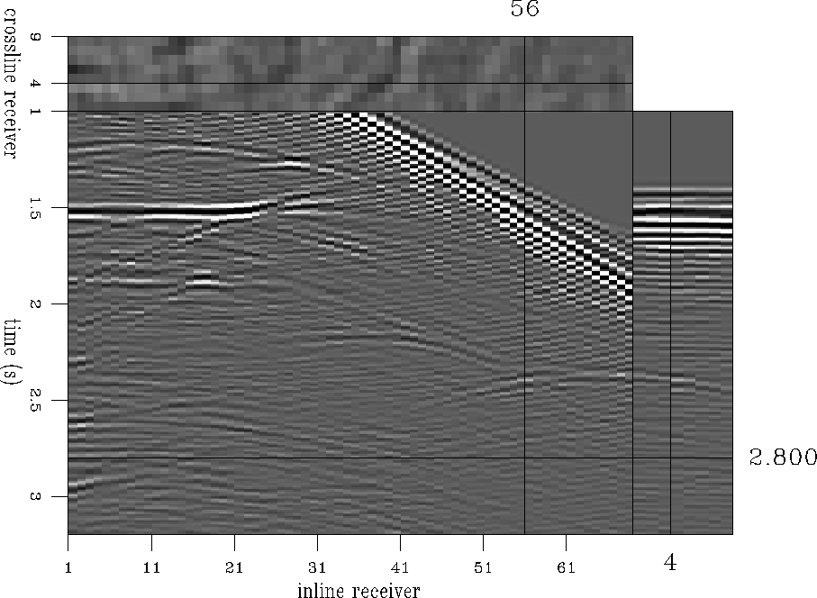
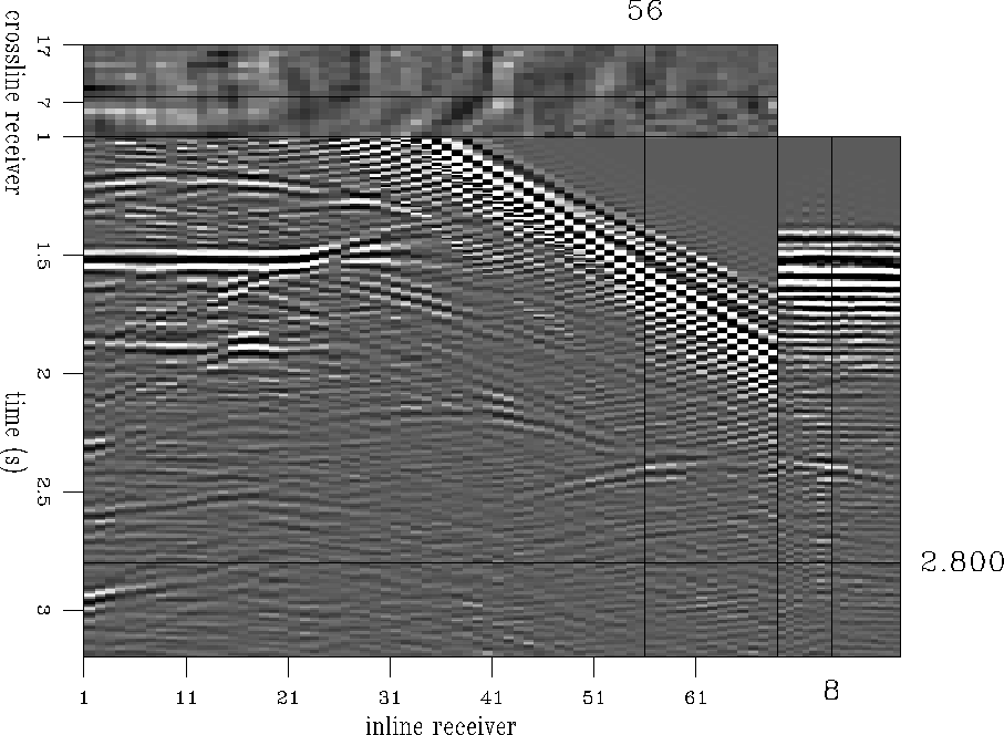
Figures m33in and m33out show a shot gather
from the SEG-AEG 3-D salt model synthetic, as modeled in the case
of Figure m33in and after interpolating streamers between
the original streamers in the case of Figure m33out.
In this case, 20 or so shot gathers were used in the test.
The interpolated data in this case was not modeled, so
there are no difference panels, but by inspection the interpolated
data seems reasonable.
The front face of the two figures do not show exactly the same inline.
Instead, Figure m33in shows a particular streamer, and Figure
m33out shows a streamer that was interpolated next to it.
m33in
Figure 14 Closeup on a marine 3-D shot gather.
Input to the crossline interpolation.


 m33out
Figure 15 Closeup on a marine 3-D shot gather.
Output of the crossline interpolation.


Next: Smoothing and damping, accuracy
Up: Data examples
Previous: Marine 3-D shot interpolation
Stanford Exploration Project
1/18/2001


