|
vel3
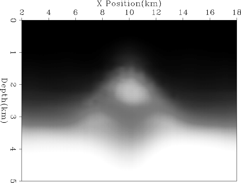
Figure 14 Velocity model after three non-linear iterations of non-stationary filter regularization. |  |
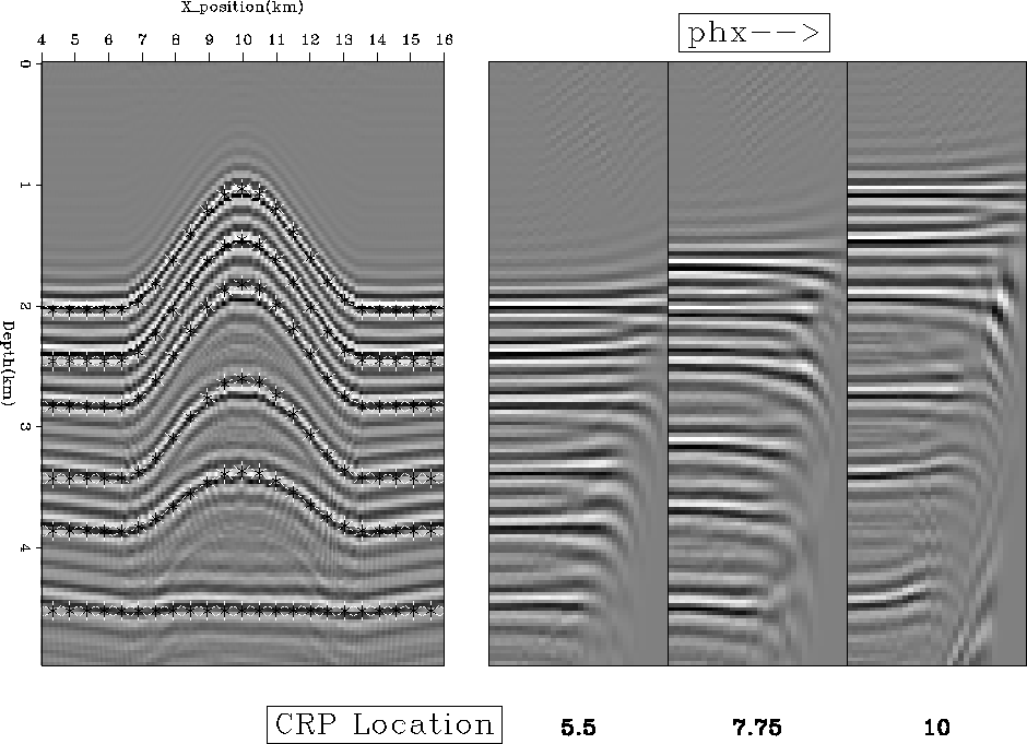
If we do three non-linear iterations of tomography using fitting goals (8) each time, we get Figure 14 as our velocity estimate. The velocity estimate does a good job recovering the anticline shape. However, it doesn't do a good job recovering the low velocity layer. Migrating with Figure 14 we get Figure 15. Overlaid on top of the migrated image are the correct reflector positions. Overall we did a good job positioning the reflectors. In addition, we can see that we have little residual moveout in our CRP gathers (Figure 15) but they are relatively flat.
|
vel3
Figure 14 Velocity model after three non-linear iterations of non-stationary filter regularization. |  |
 |