| |
(1) |
Each point on a wavefront can be parametrized by either its
Cartesian coordinates x, y, and z, or its ray
coordinates, which consist of the traveltime ![]() , and the two
shooting angles at the source,
, and the two
shooting angles at the source, ![]() and
and ![]() .
.
For complex velocity fields, the ray coordinates as a function of the Cartesian coordinates become multi-valued, in other words, there is more than one ray going through a given point in the subsurface. In contrast, the Cartesian coordinates as a function of the ray coordinates remain single-valued, that is, there is one unique position in the subsurface where a ray, shot with two particular shooting angles, arrives at a given time. Figure 1 illustrates the difference between the two representations of the wavefronts.
 |
Since ![]() ,
, ![]() , and are uniquely defined for arbitrarily complex
velocity fields, the eikonal equation (Equation 1)
can be transformed to another form that is better suited for analysis
in ray coordinates Sava and Fomel (1998):
, and are uniquely defined for arbitrarily complex
velocity fields, the eikonal equation (Equation 1)
can be transformed to another form that is better suited for analysis
in ray coordinates Sava and Fomel (1998):
| |
(2) |
Converting equation (2) to a finite-difference equation using a first-order discretization scheme, we obtain
| |
(3) |
According to the Huygens principle, the new wavefront is the envelope of all the secondary wavefronts. Mathematically, the position of the new wavefront is described by a system of three equations composed of Equation (3) and the following two equations Sava and Fomel (1998):
 |
||
| (4) |
 |
||
| (5) |
|
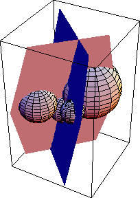
huygens3d
Figure 2 A geometrical updating scheme for 3-D HWT in the physical domain. Five points on the current wavefront, represented by the five spheres, not all visible, with radii defined by the velocities at the corresponding points of the wavefront, are used to compute a point on the next wavefront. The sphere in the middle represents equation (3), and the planes represent equations (4) and (5). |  |
Five points on the current wavefront, represented by the five spheres, not all visible, with radii defined by the velocities at the corresponding points of the wavefront, are used to compute a point on the next wavefront. The sphere in the middle represents equation (3), while the planes represent equations (4) and (5).
Huygens wavefront tracing, based on the system of equations (3), (4), and (5), is nothing but an explicit finite-difference method in the ray coordinate system. The coordinates of the new wavefronts are computed according to those of the current wavefront.
 |
A three-point stencil is needed in two dimensions to compute the centered finite-difference representation of the derivative with respect to the shooting angle, while a five-point stencil is needed in three dimensions to compute the centered finite-difference representation of the derivatives with respect to the shooting angles. Figure 3 is a graphical illustration of the finite-difference stencils.