 |
 |
 |
 | Migration velocity analysis for anisotropic models |  |
![[pdf]](icons/pdf.png) |
Next: Numerical test
Up: Li and Biondi: Anisotropic
Previous: Migration Velocity Analysis for
As mentioned in the previous section, we estimate the optimum earth model by
minimizing a user-defined image perturbation. There are many ways to
define the objective function. Here we use the Differential Semblance
Optimization (DSO) method (Shen, 2004; Symes and Carazzone, 1991) as the criterion:
 |
(20) |
where  is the identity operator and
  is the
differential operator along the angle axes in the ADCIGs
is the
differential operator along the angle axes in the ADCIGs  . In the
subsurface-offset domain, the objective function (Equation
8) reads:
. In the
subsurface-offset domain, the objective function (Equation
8) reads:
 |
(21) |
where  is the absolute value of subsurface-offset, and
 is the
image gather in the subsurface-offset domain. This operator is
preferred by many researchers since it is a fully automated
procedure, with no picking required. However, for isotropic migration
velocity analysis, many authors (Vyas and Tang, 2010; Fei and Williamson, 2010) observe
undesired artifacts generated by the DSO operator and suggest that a
differential operator along
can help compensate for the
phase shift caused by the velocity perturbation. Therefore, we use the
modified DSO operator as follows:
is the
image gather in the subsurface-offset domain. This operator is
preferred by many researchers since it is a fully automated
procedure, with no picking required. However, for isotropic migration
velocity analysis, many authors (Vyas and Tang, 2010; Fei and Williamson, 2010) observe
undesired artifacts generated by the DSO operator and suggest that a
differential operator along
can help compensate for the
phase shift caused by the velocity perturbation. Therefore, we use the
modified DSO operator as follows:
 |
(22) |
where 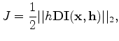 is a differential operator in
  . Taking the derivative
in the subsurface offset domain is equivalent to an
. Taking the derivative
in the subsurface offset domain is equivalent to an  weighting
in the angle domain. Therefore, the objective function (Equation 22) also
emphasizes the contribution of the large angle information, which is
crucial for velocity analysis.
weighting
in the angle domain. Therefore, the objective function (Equation 22) also
emphasizes the contribution of the large angle information, which is
crucial for velocity analysis.
To guarantee a smooth inversion, we choose a B-spline representation of
the model space. The smoothed gradient in the original space is then represented as:
 |
(23) |
where  and
and
 are the original and the smoothed
gradient on the original model grid;
are the original and the smoothed
gradient on the original model grid;  is the B-spline projection
operator. Then the number and spacing of the B-spline nodes control the
smoothness of the model update. Practically, we can choose different
B-spline parameters for velocity and
is the B-spline projection
operator. Then the number and spacing of the B-spline nodes control the
smoothness of the model update. Practically, we can choose different
B-spline parameters for velocity and  .
.
|
|
|
|
| Migration velocity analysis for anisotropic models | |
|
Next: Numerical test
Up: Li and Biondi: Anisotropic
Previous: Migration Velocity Analysis for
2011-05-24