![[*]](http://sepwww.stanford.edu/latex2html/foot_motif.gif) &
Karl Fuchs
&
Karl Fuchs![[*]](http://sepwww.stanford.edu/latex2html/foot_motif.gif)
Author has no known email address
![[*]](http://sepwww.stanford.edu/latex2html/prev_gr.gif)
![[*]](http://sepwww.stanford.edu/latex2html/foot_motif.gif) &
Karl Fuchs
&
Karl Fuchs![[*]](http://sepwww.stanford.edu/latex2html/foot_motif.gif)
ABSTRACTWave propagation in heterogeneous media is not only characterized by reflection, transmission and conversion of seismic energy but also by effects such as scattering and tunneling and can be observed on many scales. We investigate elastic wave propagation in the lower crust of the earth. It is remarkable that distance and time scales in a deep crustal reflection problem can be easily transformed into an exploration/production oriented problem. In that analog, the lower crust corresponds to some fractured medium or a medium with laminated inter bedding of source rocks, such as, sand and shale.We model surface seismic reflection data by positioning the source close to the surface. Wide-angle refraction data are simulated by placing the source into the lower crust. Teleseismic data are generated by having a plane or point source beneath the target zone. On that scale, a source with a frequency of 1Hz essentially sees an equivalent homogeneous medium, while a source with a dominant frequency of 5Hz, sees fine scale discontinuities as observed in various real data. Using a finite-difference technique, we employ models with spatially varying subsurface parameters. The fine scale heterogeneities are thin reflector segments, whose length and distance from each other are governed by a Poisson's probability distribution. Wave type conversions are surprisingly well confined and can be easily identified in seismograms as on snapshots. The ultimate goal of this investigation is to determine whether we can image those reflector segments and determine their Vp/Vs ratio. |
Modern reflection surveys of the crystalline continental crust - e.g. COCORP (), BIRPS (), DEKORP (), ECORS () - have revealed a fine structure of the crust which was previously not noticed in the classical refraction seismic sounding of crust and upper mantle. A prominent discovery was the unexpected disparity between the reflective images of the upper and lower crust, especially in extensional tectonic regimes. A strong and widespread reflectivity characterizes the lower crust, typically in a frequency band from 5 to 15 Hz, while the upper crust appeared mostly as ``transparent'' with occasional occurrence of discrete reflectors. The outstanding reflectivity of the lower crust was explained by a sequence of lamellas of about a quarter wavelength giving rise to constructive interference of multiple reflections in between thin layers.
A first attempt to observe and analyze the effect of the lamellas in wide-angle refraction data was presented by Sandmeier & Wenzel . Starting from a laminated model of the lower crust, which explained the observed near-vertical reflection patterns, they could identify reverberations in wide-angle observations reverberations between the two reflection branches from the top (PCP) and the bottom (PMP) of the lower crust. The surprise in their synthetic seismogram modeling was that these reverberations did occur in the P-branch but not in the corresponding S-branches, although the primary SCS and SMS could be clearly recognized in the observed data. From this discrepancy between P- and S-wave behavior they deduced that the lamination of the lower crust is primarily visible in the P-wave and not in the S-wave field.
As wide-angle refraction experiment developed recently towards higher resolution by denser station spacing, the study of the heterogeneities of the lower crust revealed more details of their properties. A remarkable observation was made by Novack during the interpretation of wide-angle refraction data obtained in the French Massif Central. Trying to model strong PCP-reflections which reached from supercritical to subcritical distance range, he found that:
Nature of the Reflective Lower Crust Many conjectures have been brought forward to understand the origin and nature of this reflective sequence of high and low velocity lamellas, which range from horizontal basaltic injections into the lower crust to the occurrence of free fluids in extended horizontal pockets (, ). Figure schema outlines a simple schematic model and shows the experiment types (Fig. martin5b-martin2aR) in which we are interested in. The difference between the reflection images of upper and lower crust were also considered to be a manifestation of the contrast in rheological regimes of the two subdivisions of the crystalline crust: the upper part belongs to the brittle tectonic regime which yields to stress by fracture along discrete planes, while the lower crust is governed by the ductile regime where stresses are decreased by flow mainly of quartz rich rocks (, , , ). This flow on nearly horizontal glide planes could contribute to the formation of horizontal lamellas. Even vertical injections into the lower crust could obtain horizontal shapes by the flow mechanism.
PROBLEMS
From the observed reflectivity pattern of the lower crust, the lateral extent of the lamellas may be estimated to be about a few kilometers, certainly less than 10 km. This observation has so far not been taken into account in synthetic seismogram calculations of near-vertical reflections from the lower crust.
In comparison to refraction studies in the same location the following observations are important for a better understanding of the nature of the the lower crust's reflectivity. The origin of the unusually strong reflections from the Mohorovicic discontinuity (Moho) were of concern from their very early discoveries () to tailored experiments (, ), and are still discussed in reviews (, ). The top of the reflective lower crust appears to be coinciding with the so-called Conrad discontinuity (Conrad) having refraction arrivals corresponding to a velocity of about 6.5 km/s. The lower boundary of the reflective lower crust coincides in many parallel experiments with the crust-mantle boundary (Moho) as observed in refraction surveys. The near-vertical reflections terminate rather abruptly at a time corresponding to the depth obtained from wide-angle refraction surveys in the same region. It remains an enigma about the reflective nature of the lower crust: Why is the vertical signal not carrying a coda generated during two-way passage through the laminated lower crust ?
It is noteworthy that the reverberations caused by the lower crust can concurrently appear as coda to PCP, PMP, SCS and SMS, however, in some cases, e.g. Sandmeier & Wenzel , PCP is observed in the absence of SCS. The codas of both PMP, and SMS have been recognized but not been connected so far with reverberations picked up in the lower crust.
There are three ways to study heterogeneities of the lower crust in reflection and transmission experiments: 1) near-vertical reflections, 2) wide angle-refractions, and 3) teleseismics. The latter observation is reported by Ritter et al. . They showed that teleseismic P-signals with a dominant frequency between 0.5 to 1 Hz carry a high frequency coda which is most likely generated by multiple scattering in the deeper part of the crust and is visible throughout an array of mobile three-component seismic stations.
In the present study we make an attempt to model wave propagation in a heterogeneous lower crust from those three perspectives by finite-difference (FD) calculations. The particular finite difference method used is described in detail in Karrenbach . Time-distance record sections (seismograms) as well as depth-distance snapshots allow to analyze the complex wave field generated by reflection or transmission in the lower crust.
 |
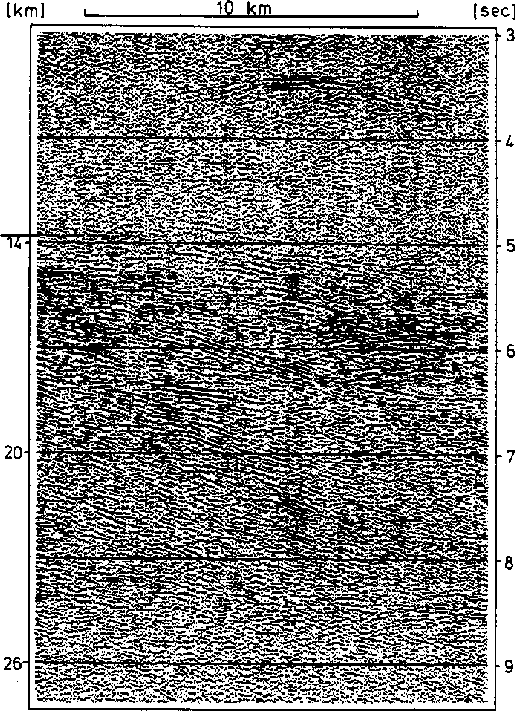
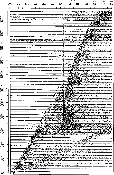
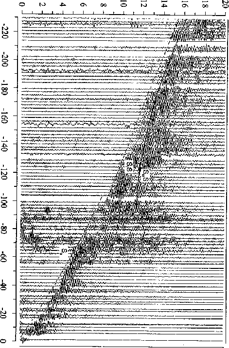
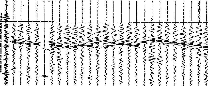
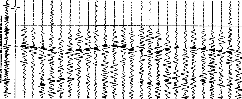
The following plots show reflection data from the Black Forest (Fig. martin5b), wide-angle refraction data (Fig. martin4b and martin3b) and teleseismic data from the French Massif Central (Fig. martin1aR and martin2aR). Note that the reverberations show up dominantly on the radial component, while on the vertical component they are hardly visible. Compare these real data set with the data obtained by finite-difference modeling later in this paper.
 |
 |
 |
 |
 |
MODEL DESCRIPTION
Basic Model
In Figure modellamr, the following basic underlying model of the
laterally homogeneous crust is used throughout this study.
| Depth | vp | vs | Density |
| (km) | (km/s) | (km/s) | (g/cm3) |
| 0-15 | 6.0 | 3.46 | 2.8 |
| 15-30 | 6.5 | 3.75 | 2.8 |
| 30-45 | 8.0 | 4.62 | 2.8 |
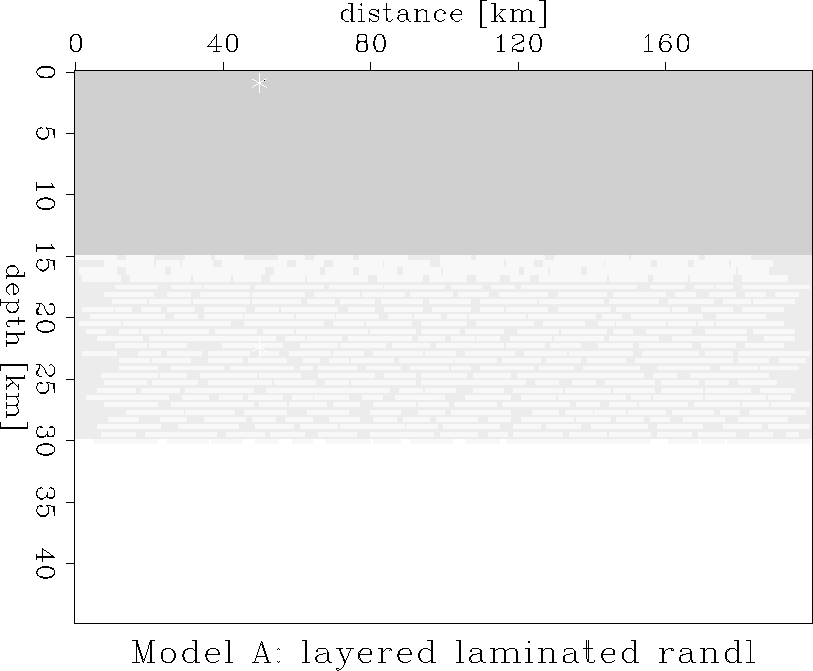 |
To model the three experiments of reflection/transmission the explosive
source is placed at the surface (near vertical reflection), in
the middle of the lower crust (shortening the critical distance) and at
a depth of 45 km (simulating transmission of teleseismic incidence from
below the Moho). The arrival of a plane wave caused by teleseismic events
is simulated by a series of densely spaced sources
dipping on a slightly inclined plane (![]() ,
, ![]() ).
To compare the low frequency and high frequency response of the lower
crust, two types of source signals were applied in the FD calculations,
one with a dominant frequency at 1 Hz and the other at 5 Hz.
).
To compare the low frequency and high frequency response of the lower
crust, two types of source signals were applied in the FD calculations,
one with a dominant frequency at 1 Hz and the other at 5 Hz.
xseis.srefl.r.5height=3.4in,width=6.inCRReflection experiment: time distance seismogram sections with explosive source (5 Hz dominant frequency) near the free surface (1 km depth); x-component. The direct P- and S-wave phases and their reflections at the model boundary have been suppressed.
 |
 |
 |
 |
 |
 |
 |
 |
 |
 |
 |
 |
 |
 |
 |
 |
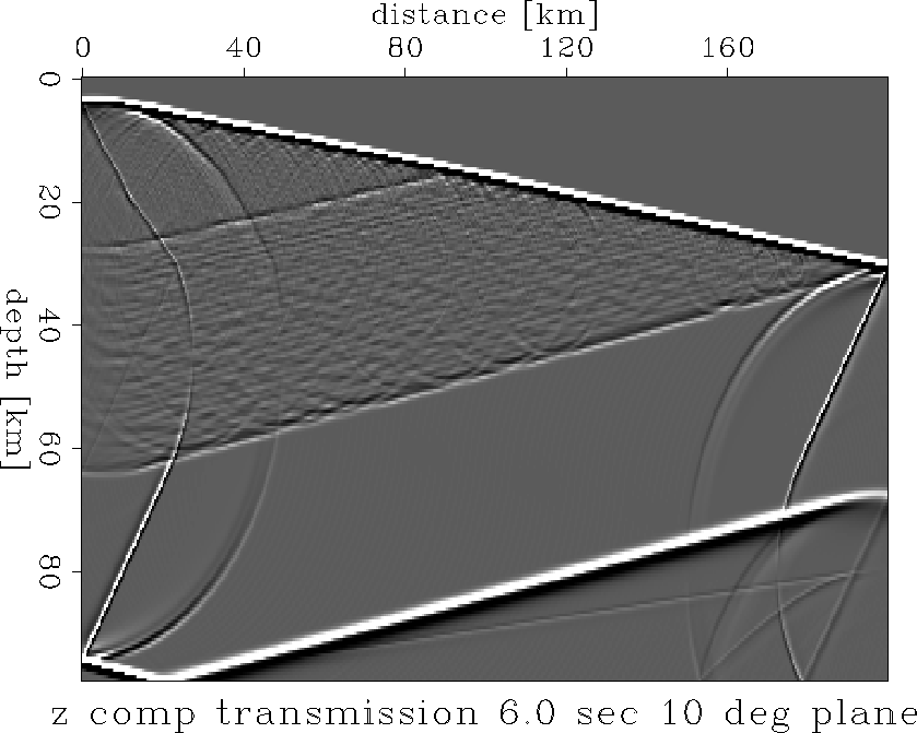 |
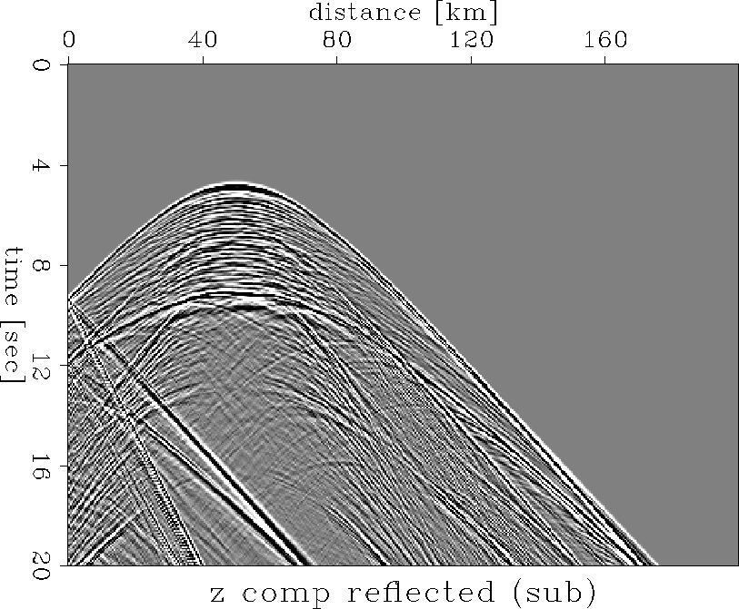
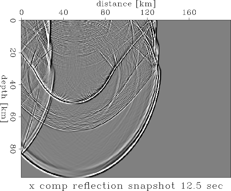
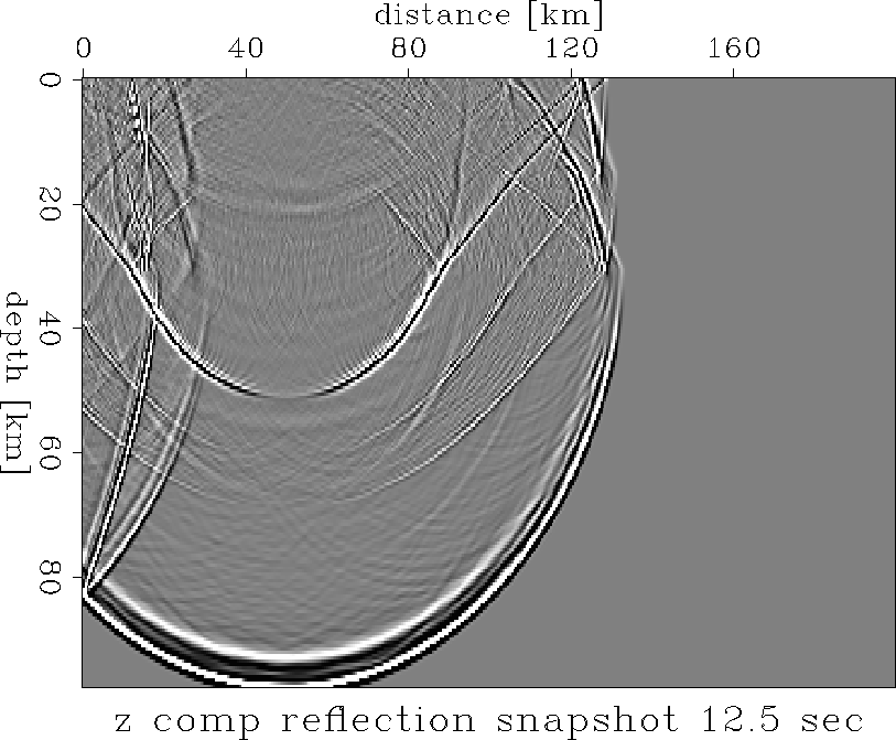
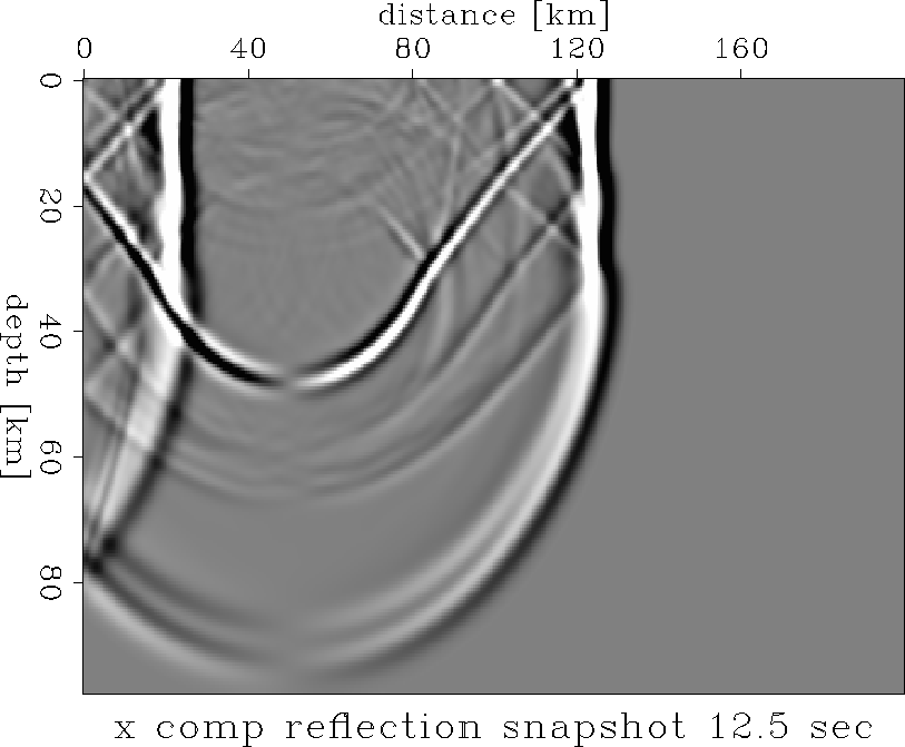
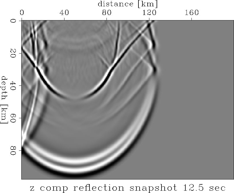
Figure xseis.srefl.r.5 and zseis.srefl.r.5 are x- and z-component seismograms, respectively, in the reflection experiment for a laterally heterogeneous crust. Both vertical and horizontal component snapshots are recorded for a high (Fig. xsnap.refl.r.5b and zsnap.refl.r.5b) and a low frequency source (Fig. xsnap.refl.r.1b and zsnap.refl.r.1b). The direct P- and S-wave arrivals as well as the reflections from the side borders are eliminated by subtracting the equivalent records for the first layer, taken as a half space, from the calculated sections.
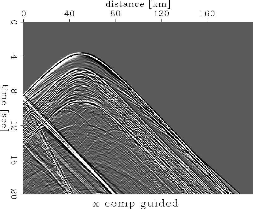
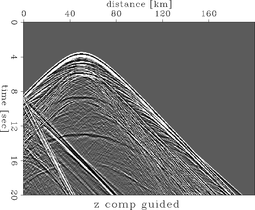
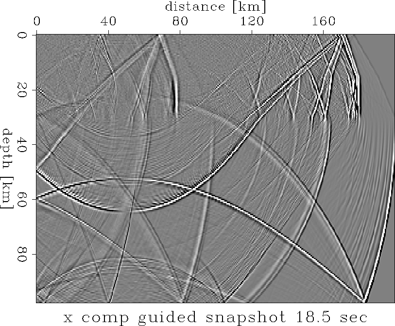
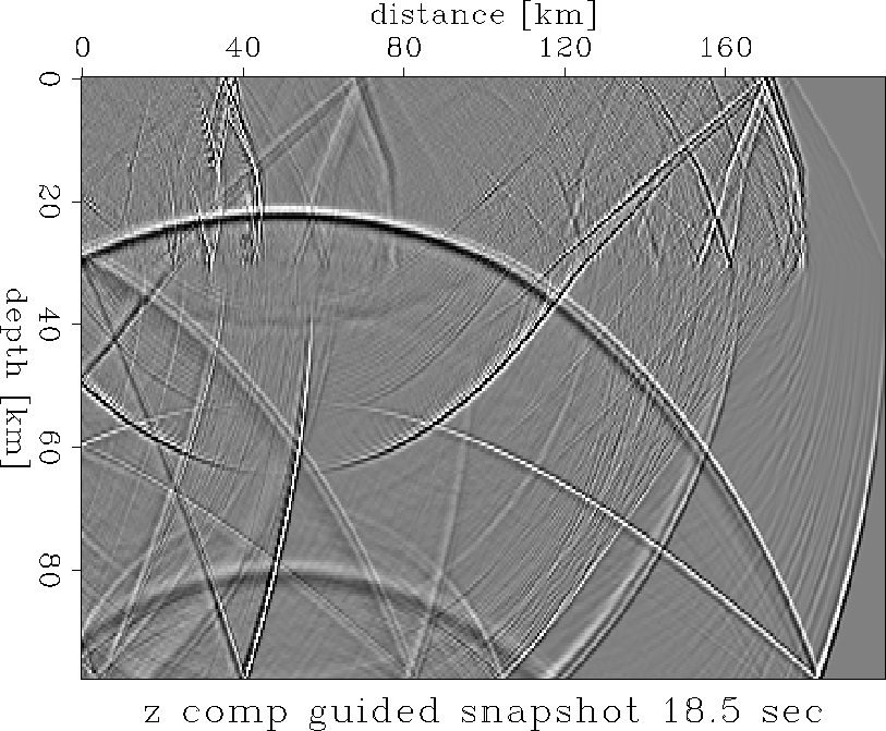
In Figures xseis.guide.r.5-zsnap.guide.r.5c the source is located in the middle of the laminated lower crust at a depth of 22.5 km, in order to simulate an extreme wide-angle experiment. The lower crust acts as a wave guide.
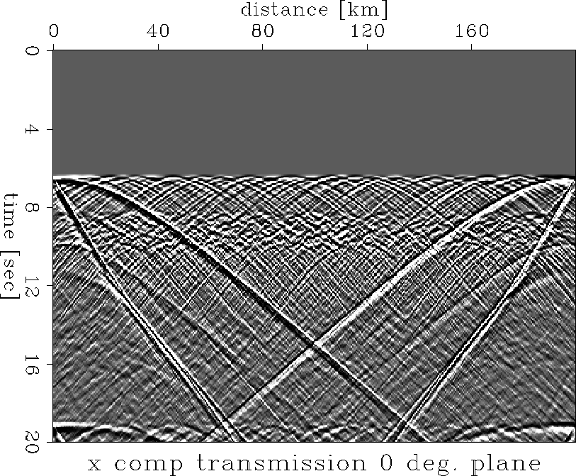
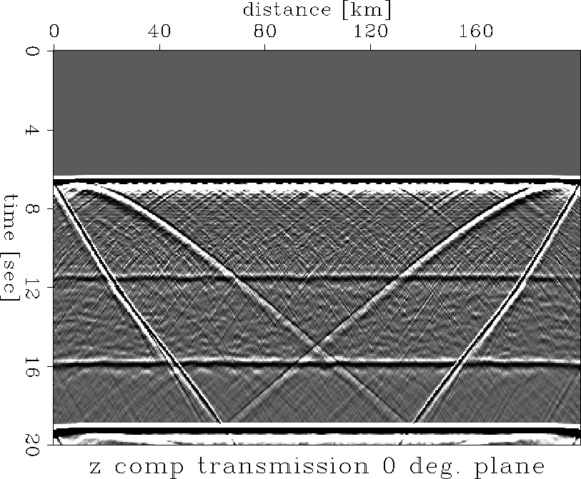
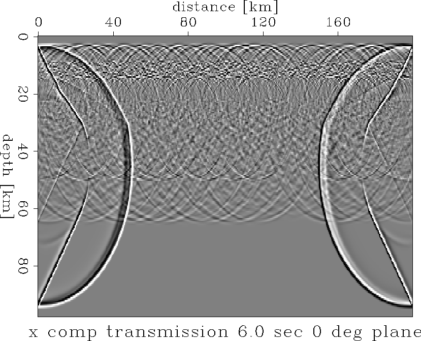
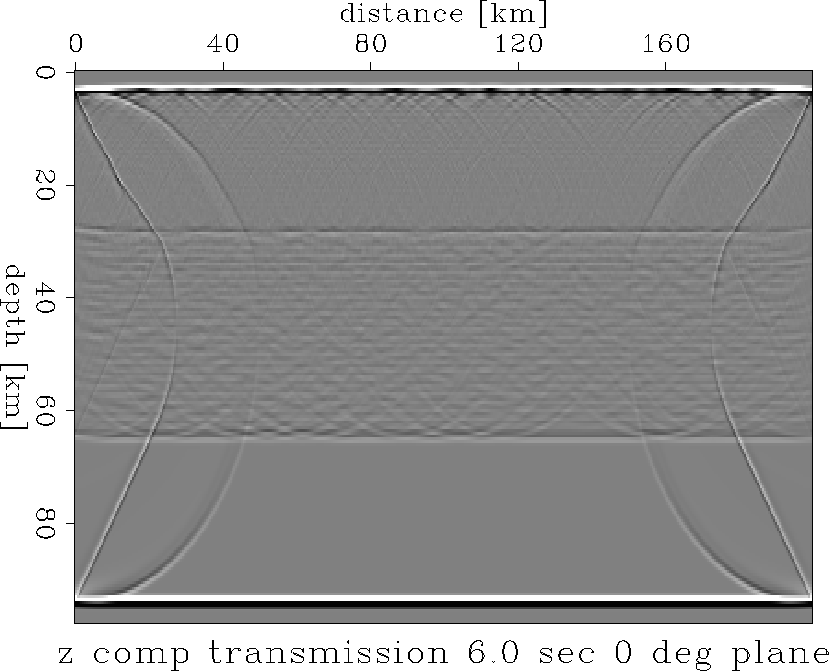
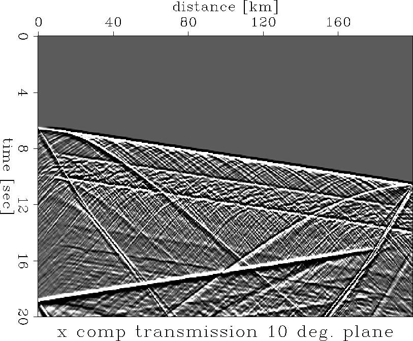
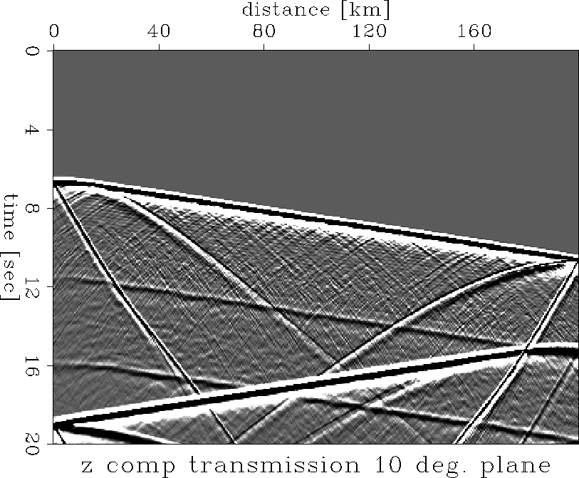
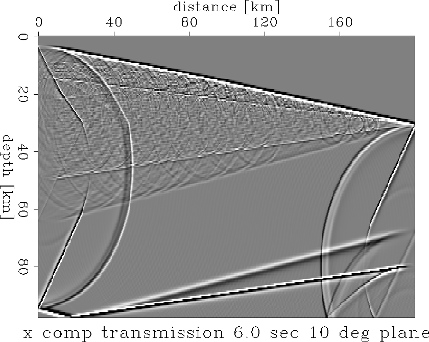
Figures xseis.tele0.r.5-zsnap.tele10.r.5d simulate teleseismic experiments.
A plane wave source is created by a dense ensemble of point sources
located along a straight line below the Moho at a depth of roughly 45 km.
In one case the line is horizontal, while in the other it is
dipping ![]() .For the reflection experiment,
the source is located 1 km below the surface.
.For the reflection experiment,
the source is located 1 km below the surface.
We can clearly identify the following distinct phases:
In the z-section (Fig. zseis.srefl.r.5) after PcP in the interval [80 km; 120 km] and [6 sec; 14 sec] appear those reverberations which Novack has seen in the Massif Central. They appear also after PMP n the interval [150 km; 170 km] and [17 sec; 20 sec]. Sources within the laminated lower crust
The seismograms in Figures xseis.guide.r.5 and zseis.guide.r.5 are best understood by simultaneously examining the snapshots in Figures xsnap.guide.r.5c and zsnap.guide.r.5c. At 350 km the development of the head wave from the lower crust is clearly recognized with reverberations from the laminated lower crust. This corresponds very much to wave propagation in a ``peanut model'' in the topmost mantle (). The wave propagates with the mean velocity of the peanut model. The coda contains waves which range from P- to S-waves (identified from the inclination of the wave fronts). The question remains: How do these reverberations change their appearance when the parameters of the lamellas are changed: thickness, length, gaps, Vp, Vp/Vs.
Teleseismic Experiment
Angles of incidence at the base of the crust during teleseismic
observations are quite small, they actually are very close to the
angles used in near-vertical reflection experiments. However, in the
teleseismic experiments we are looking at the transmission response.
A plane wave incident vertically at 0 ![]() is modelled in Figures
xseis.tele0.r.5-zsnap.tele0.r.5d and at 10
is modelled in Figures
xseis.tele0.r.5-zsnap.tele0.r.5d and at 10 ![]() incident in Figures
xseis.tele10.r.5-zsnap.tele10.r.5d for both the
x- and z-component.
The seismogram sections are displayed in
Figures xseis.tele0.r.5, zseis.tele0.r.5, xseis.tele10.r.5 and zseis.tele10.r.5, respectively.
The snapshots at 6.0 sec are
found in Figures xsnap.tele0.r.5d, zsnap.tele0.r.5d, xsnap.tele10.r.5d and zsnap.tele10.r.5d
for both components. The best
possibility to identify the various phases is in the snapshots for
10
incident in Figures
xseis.tele10.r.5-zsnap.tele10.r.5d for both the
x- and z-component.
The seismogram sections are displayed in
Figures xseis.tele0.r.5, zseis.tele0.r.5, xseis.tele10.r.5 and zseis.tele10.r.5, respectively.
The snapshots at 6.0 sec are
found in Figures xsnap.tele0.r.5d, zsnap.tele0.r.5d, xsnap.tele10.r.5d and zsnap.tele10.r.5d
for both components. The best
possibility to identify the various phases is in the snapshots for
10 ![]() incidence in Figure xsnap.tele10.r.5d and zsnap.tele10.r.5d, because here
upward and downward
travelling waves can be distinguished clearly and comparison with the
corresponding seismograms in Figures xsnap.tele0.r.5d and zsnap.tele0.r.5d
is facilitated.
The band ends sharply with the phase converted from P-S at the Moho (PMS).
The described three kind of phases belong to the transmitted energy which
is recorded at the free surface and can also be recognized in the
corresponding seismograms.
In addition to the transmitted converted phases there are also downward
travelling phases corresponding to reflection and conversion at the top
and bottom of the lower crust. These reflected phases return into the upper
mantle and can not be seen in the record sections.
Comparison of the snapshots for the x-component (Figure xsnap.tele10.r.5d) and
the z-component
(Figure zsnap.tele10.r.5d) shows that the codas both of P-diffracted and of PCS- and
PMS-type are much more clearly seen in the horizontal component. This
has two different reasons: the P-coda following the direct P-wave is
built up by strong P-diffractions with an appreciable horizontal component
from off-ray diffractions; on the other hand the S-band coda actually
has a dominant horizontal component in itself.
The band reflected into the mantle appears much broader
because it travels with mantle velocity.
incidence in Figure xsnap.tele10.r.5d and zsnap.tele10.r.5d, because here
upward and downward
travelling waves can be distinguished clearly and comparison with the
corresponding seismograms in Figures xsnap.tele0.r.5d and zsnap.tele0.r.5d
is facilitated.
The band ends sharply with the phase converted from P-S at the Moho (PMS).
The described three kind of phases belong to the transmitted energy which
is recorded at the free surface and can also be recognized in the
corresponding seismograms.
In addition to the transmitted converted phases there are also downward
travelling phases corresponding to reflection and conversion at the top
and bottom of the lower crust. These reflected phases return into the upper
mantle and can not be seen in the record sections.
Comparison of the snapshots for the x-component (Figure xsnap.tele10.r.5d) and
the z-component
(Figure zsnap.tele10.r.5d) shows that the codas both of P-diffracted and of PCS- and
PMS-type are much more clearly seen in the horizontal component. This
has two different reasons: the P-coda following the direct P-wave is
built up by strong P-diffractions with an appreciable horizontal component
from off-ray diffractions; on the other hand the S-band coda actually
has a dominant horizontal component in itself.
The band reflected into the mantle appears much broader
because it travels with mantle velocity.
OBSERVATIONS
In Figures xseis.srefl.r.5 and zseis.srefl.r.5 the direct P-and S-wave phases and their effects at the model border have been suppressed. Therefore, the first arrival is the PCP reflection from the top of the lower crust. It is followed by the reverberating response from the lower crust. In the vertical component section (Fig. zseis.srefl.r.5) this band ends rather abruptly near-vertical incidence. This termination coincides with the two-way-traveltime (TWT) from the Moho. For the horizontal component (Fig. xseis.srefl.r.5) the lower crustal reverberations continue beyond the PMP time. They seem to be terminating only after the SMS reflection from the Moho.
This behavior can be observed even more clearly in the snapshots at 6.5 sec. In Figure zsnap.refl.r.5b the band of reverberating energy returning from the lower crust is bounded by the PMP reflection, while in the section for the horizontal component (Fig. xsnap.refl.r.5b) the coda extends beyond PMP. We can notice that the downward travelling S-phases (converted from P to S in the lower crust) generate here continuously a band of upward propagating S-energy.
Note that the low frequency wave field (Fig. xsnap.refl.r.1b and zsnap.refl.r.1b) practically does not sense the heterogeneities in the lower crust, and that PMP reflection becomes almost unobservable. Only the termination of the heterogeneities at the bottom of the lower crust causes the appearance of the PMP reflection in near-vertical reflection experiments.
If the PS-scattered energy is reaching the Moho (6.5/8.0 km/sec interface)
the critical angle for S-to P-reflection and generation of a connected
headwave is 31 ![]() in contrast to 60.4
in contrast to 60.4 ![]() for the PP reflection .
The first diffracted and critically SP reflected energy becomes
visible at about a distance of 15 km. At smaller distances the reflection
of the diffracted wave is subcritical and therefore, less effective.
for the PP reflection .
The first diffracted and critically SP reflected energy becomes
visible at about a distance of 15 km. At smaller distances the reflection
of the diffracted wave is subcritical and therefore, less effective.
The numerical experiments in Figures xseis.guide.r.5 and zsnap.guide.r.5c were conducted to study the behavior of the wave field at distances where the Pn headwave from the upper mantle becomes a first arrival.
Reflection from the Moho - scattered and reflected wave field
The investigation of the heterogeneities of the lower crust and the crust-mantle boundary (Moho) in near-vertical reflection and wide angle refraction experiments poses two essential problems for the nature of the reflections from the crust-mantle transition. The laminated heterogeneities of the lower crust cause the reverberating reflectivity seen in near-vertical reflection experiments. They produce a coda to PCP and PMP in wide-angle refraction experiments, and generate also a high frequency coda of teleseismic phases. Wherever near-vertical and wide-angle observations are available in the same region (), the observed zero-offset TWT in near-vertical reflection surveys is compatible with the calculated zero-offset TWT deduced from observed supercritical PMP reflections and Pn headwaves. However, there is an important difference between the near-vertical and supercritical reflections: in the first case the PMP reflection is preceded by the lower crustal reverberations and terminates abruptly without a coda, while in the second case the reverberations form a well-developed coda to PMP with the primary sharp signal at its beginning.
The abrupt termination of the P-reflectivity of the lower crust at near-vertical incidence is very frequently observed in deep crustal reflection work. In fact this termination of the lower crustal reflectivity pattern at near vertical incidence is taken as ``the reflection from Moho''. Why do the reverberations from the lower crust stop so abruptly on the z-component, i.e. in the P-field? Why does the near-vertical reflection from the Moho not carry a coda of transmitted scattered, converted and multiply reflected phases, in short: reverberating energy?
The primary P-wave incident into the lower crust is scattered at its heterogeneities. A forward scattered part following the primary P-signal downward is to be distinguished from a backscattered part traveling upward. The lower crust ``tunes-in'' to that part of the signal spectrum which magnifies the scattered field by constructive interference. This part is seen, for example, in the near-vertical reflection experiments.
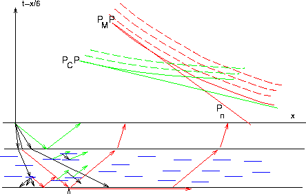 |
The answer to this paradox is: there is practically no observable reflected energy from the Moho at near-vertical incidence, but only backscattering of type PP or PS out of the lower crust in constructive interference in that favorable frequency band.
Apart from the primary P-wave, an ensemble of scattered or diffracted waves of both P and S types generated within the lower crust is reaching the crust mantle boundary (Moho). However, when this primary wave and its coda arrive at near-vertical incidence at the crust-mantle boundary the reflection coefficient is only about 0.2. In comparison to the tuned reflectivity of the lower crust, the primary reflection from the Moho and its coda is lost in signal generated noise.
In Fig. zseis.srefl.r.5 (vertical component), at near-zero distance from the source the reverberations from the lower crust are seen between the PcP and the PMP reflections. At the PMP time the reverberations in the z-component terminate rather abruptly with a small indication of amplitude increase right at the end. The reverberations between PcP and PMP are predominantly PP-scattered at the individual heterogeneities in the lower crust, directly returned to the surface, while the primary signal is passing through the heterogeneous medium. In Fig. xseis.srefl.r.5 (horizontal component) the reverberations continue beyond PMP bounded by ScS.
The situation for the reflected primary P-signal with its coda generated in the lower crust becomes different as soon as its angle of incidence becomes supercritical. The PP-reflection coefficient approaches unity: the primary signal together with its coda becomes clearly visible.
The most effective angles for the return of P-or S-energy to the surface are those of critical to supercritical incidence at the Moho. Energy incident at less than the critical angle will not contribute to the received signal compared to those of supercritical incidence. Since scattered waves are following the primary P-wave and since every scatterer in the lower crust causes a pattern of diffracted energy propagating in all directions, critically reflected energy may also occur at distances smaller than the ``critical distance'' sensu stricto. The two bundles of P- and S-waves reaching the Moho at supercritical angles will be reflected by the Moho most effectively. Since the scatterers may be located practically at zero distance from the Moho, the first appearance of critically diffracted P-energy is expected at 37.9 km and that for supercritical PS-conversions at 15.2 km from the location of the diffractor near the Moho.
In Summary:
We have shown that we adequately model elastic wave propagation effects in the lower crust of the earth. We use a finite difference method in modeling of all dynamic elastic wave propagation effects in a 2D model. First, we verified that the scattering behavior is strongly dependent on the frequency content of the source signal. Second, we showed that the scattering behavior varies for different wave types and that the scattered wave field can be separated from the total wave field. We conjecture that using imaging techniques it should be possible to determine the lateral extent of reflecting segments in the lower crust as well as estimate Vp/Vs ratio of those lamellas.
We thank the Stanford Exploration Project for providing high performance computers, modeling software and seismic processing tools (SEPLIB). We enjoyed our cooperation on a wave propagation problem that is important for exploration as well as deep crustal investigations. The experimental seismic investigation in the Massif Central in France and in the Rhinegraben area were supported by the Collaborative Research Center 108 ``Stress and Stress Release in the Lithosphere'' of the Deutsche Forschungsgemeinschaft at Karlsruhe University, SFB contribution No. 414.
[SEP,MISC,refs]
![[*]](http://sepwww.stanford.edu/latex2html/prev_gr.gif)