![[*]](http://sepwww.stanford.edu/latex2html/prev_gr.gif)
ABSTRACTIn this paper I describe progress towards developing a method of inverting for complex near-surface velocity structure by combining two inversion techniques in a two-step method. The first step is based on the qualitative observation that trace power calculated from seismic data and plotted in midpoint-offset coordinates results in distinctive trajectories which depend on the position and depth of near-surface velocity anomalies. By summing along these trajectories it is possible to create an image which positions the anomalies in terms of lateral position and depth. In the second step, this image will be input to a wavefield extrapolation inversion routine as a preliminary velocity model. Once the velocity structure is estimated, the seismic data can be numerically propagated through it to remove distortions caused by focusing and kinematics effects. I present examples of downward continuing synthetic data through near-surface velocity models using both Kirchhoff and finite-difference wavefield extrapolation methods. |
In many areas, the quality of seismic data and the utility of its interpretation are adversely affected by propagation through complex near-surface geology. The propagation produces focusing, kinematic, and amplitude effects that adversely affect lithological and structural interpretation. Many oil and gas reservoirs are difficult to characterize and delineate properly because of this distortion. The objective of the method described here is to accurately estimate near-surface velocity and allow distortions to be removed from seismic data.
In many oil producing regions of the world, such as in the Mississippi Delta, significant near-surface velocity anomalies distort seismic data. These distortions cause amplitude and focusing effects that convey false structural and lithologic information. For example, kinematic effects can distort structure, and focusing effects can alter amplitude versus offset (AVO) effects. These problems cause errors in reservoir delineation and lithologic interpretation, which can lead to costly mismanagement of enhanced oil recovery (EOR) and exploitation projects.
Conventional seismic processing practice aims to compensate for near-surface effects by applying static shifts to the data; however, this method is only appropriate when the effects of the near-surface are purely kinematic. This is only the case when the velocity anomalies occur at the surface and when the wave propagation through the anomalous regions is nearly vertical. When near-surface structure causes focusing effects, the problem can be handled properly only by treating it as a wave propagation phenomenon.
The effect of near-surface velocity variations was investigated by Kjartansson , who showed that shallow absorption or velocity anomalies can masquerade as bright spots, which are usually associated with gas-bearing zones. In his study he found that the anomalies caused an AVO effect that cannot be explained by angle dependent reflectivity but which adversely affects the stacking process of seismic imaging. Kjartansson estimated the location of the anomalies, but did not determine any velocity variation associated with them, and did not try to compensate for the effects of the anomalies in any way.
Seismic imaging algorithms are generally applied to data which is redatumed to a planar surface. In regions of mild topography where the near surface velocity is much slower than the subsurface velocity, a static shift is adequate for the transformation. However, when the necessary shift increases in magnitude and when the near surface velocity is comparable to or higher than the subsurface velocity, the static approximation becomes inadequate. Under these circumstances, a static shift distorts the wavefield and degrades the velocity analysis and imaging. In this case it is necessary to numerically propagate the wavefield to some level datum. This wave-equation datuming process may be used to downward continue the data through the near surface or to ``flood'' the topography by filling it with a replacement velocity and upward continuing the data (, , ). In either case, the velocity for downward continuation or upward continuation must somehow be determined. The near-surface velocity estimation scheme proposed here can be applied to determine an appropriate near-surface velocity model. The data can then be redatumed using this velocity and the distortions due to topography and near-surface velocity can be suppressed.
The potential advantages of wave-equation redatuming of land data have been recognized for some time (, , ) but it has not seen widespread application because of the difficulty of determining the near-surface velocity to use in the datuming algorithm. The problem has been a circular one because the velocity must be known in order to do the datuming; however, using conventional processing techniques, the velocity cannot be determined until after the datuming has been performed. Conventional near-surface velocity determination methods, such as refraction analysis, often fail when topographic relief is substantial because the propagation modes no longer fit the assumptions of the refraction inversion algorithms ().
The method I am developing is a way of performing a nonlinear inversion for near-surface velocity structure. Since the goal of the method is to invert only for the near-surface, it may be more realizable than methods which invert for the entire geological model.
In this paper, I use a simple synthetic model to examine how data can be propagated through near-surface velocity perturbations in order to remove unwanted distortions.
SYNTHETIC EXAMPLE In SEP-79 a two-step method of estimating near-surface velocity is proposed (, ). First, a preliminary near-surface velocity distribution is estimated by performing an inversion based on a simplified model of near-surface propagation. The output of this step is an image which positions the anomalies in terms of depth and lateral position. In the second step, this image is input to a wavefield extrapolation inversion routine as a preliminary velocity model. The first step localizes the objective function, putting it in a convex region so the wavefield can then be iteratively propagated through the near surface model with the second step until a solution is converged upon. To facilitate discussion, I will call this method the Near-Surface Velocity Inversion (NSVI) algorithm.
In this section, I will briefly outline the method of generating the synthetic data used in this paper (For a more complete discussion, see Bevc ). The model used for this example consists of two reflectors in a constant velocity media and a near-surface velocity perturbation (Figure model). The velocity perturbation is a low-velocity zone bounded by two Gaussian shaped surfaces.
A Kirchhoff modeling program was used to
generate a suite of synthetic shot gathers.
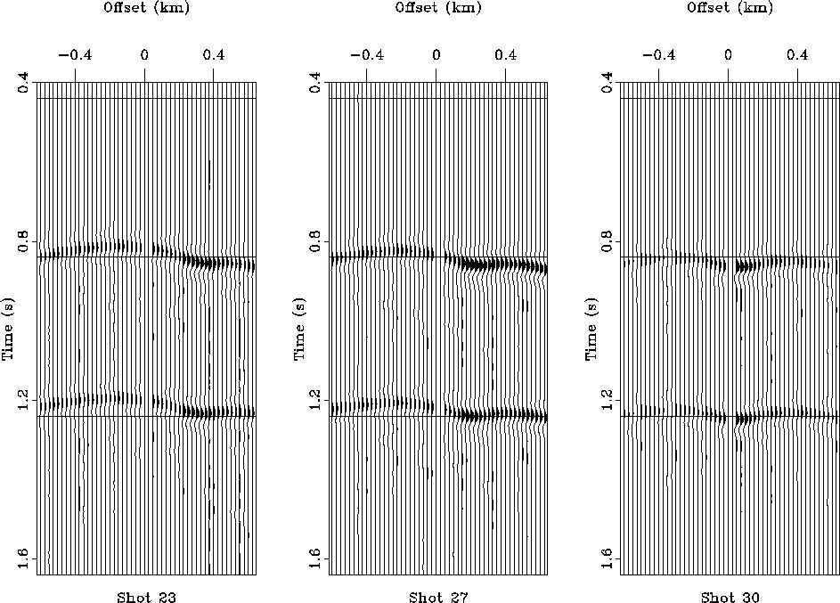
If there were no near-surface velocity perturbation, the shot gathers
would exhibit normal hyperbolic moveout; however, because of the
low-velocity perturbation, the shot gathers in Figure shot
exhibit timing and focusing effects. Because of the focusing effects,
a static shift of the data is not adequate to correct
for the velocity perturbation. For different shot locations, the effect of the
perturbation is different. This observation suggests that there should be
some way to localize the anomaly by using the information from all the
different shots and receivers.
The first step of NSVI is based on this observation.
To perform the first step,
trace power is calculated in a time window around a given reflection event.
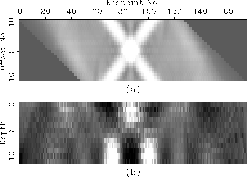
The result of doing this for the simple synthetic is displayed in
Figure tomoa. For a split-spread acquisition geometry a velocity
anomaly gives rise to an X-pattern. For deeper anomalies the legs of
the X would be closer to the midpoint axis. For shallower anomalies
the legs of the X would be closer to the ![]() lines representing
the shot and group axes (, ).
lines representing
the shot and group axes (, ).
|
model
Figure 1 Two horizontal reflectors at depths of 0.8 km and 1.2 km are represented by solid lines. The medium velocity is 2 km/s everywhere except between the two dashed lines centered at a depth of 0.2 km where it is 1.5 km/s. | 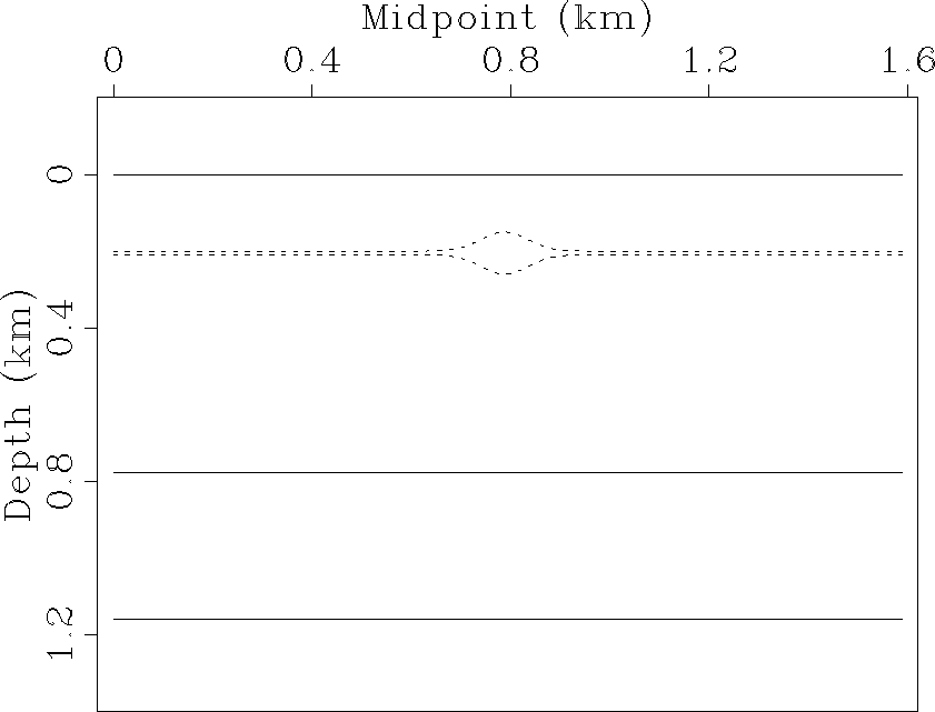 |
 |
Because the dip of the X pattern in Figure tomoa can be interpreted as a measure of depth, it is possible to image near-surface velocity perturbations by performing dip-dependent line integrals (slant stacks) of the power plots (). The idea is that energy aligned along the midpoint axis is caused by anomalies at depth, and energy aligned closer to the shot and geophone axes is caused by shallow anomalies.
The result of the slant stack inversion is presented in Figure tomob. The image of the anomaly occurs directly below the center of the X and exhibits artifacts at the bottom of the plot which are due to data truncation. This simple synthetic has only a few offsets, if more offsets were taken into the inversion, the image resolution would improve and artifacts would be reduced.
 |
The second step of the proposed NSVI method is to input the initial image from the slant stack inversion into an iterative wavefield extrapolation program as a first guess of the velocity structure.
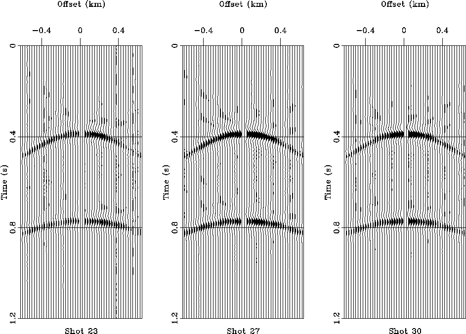
In Figure syndn, I demonstrate how the distortions caused by the velocity perturbation can be removed by downward continuing the data through the exact velocity model. In that figure, I have taken the data from Figure shot and downward continued it through the exact near-surface velocity model using a Kirchhoff datuming algorithm. The kinematic effects of the velocity perturbation are removed, but some focusing effects remain. This may be partially because the adjoint of the modeling process was used to downward continue the data, not the inverse. This forms the basis of the proposed iterative wavefield inversion algorithm. The wavefield will be iteratively propagated through the near-surface until a velocity model which results in hyperbolic trajectories is converged upon. For more complicated geological settings the objective function could optimize velocity analysis or prestack migration.
 |
After the data are downward continued through the near-surface with the correct velocity, the kinematic and amplitude distortions are removed and AVO, velocity, or structural interpretation can be successfully performed.
FINITE-DIFFERENCE EXTRAPOLATION
In order to develop an iterative velocity inversion scheme, it is necessary
to have a flexible way of parameterizing the near-surface velocity model.
In this section I show examples of using a ![]() finite-difference
wavefield extrapolation routine to downward continue the synthetic data
and perform layer replacement.
finite-difference
wavefield extrapolation routine to downward continue the synthetic data
and perform layer replacement.
Layer Replacement The velocity model used for the downward continuation is shown in Figure fdvelfig. The velocity ranges from 1.5 km/s (black) to 2.0 km/s (white). The result of downward continuing the synthetic shot gathers of Figure shot through this model is shown in Figure fddown. These results are not as nice as the ones shown in Figure syndn because now I am not using the adjoint of the method that was used to generate the synthetic for the downward continuation. Fewer offsets were input to the finite-difference downward continuation, so the results in Figure fddown also suffer from limited aperture.
|
fdvelfig
Figure 5 Velocity model used for the finite-difference downward continuation. The velocity model used for the Kirchhoff modeling is shown with dashed lines. The finite-difference velocity model corresponds to thirty two depth steps. | 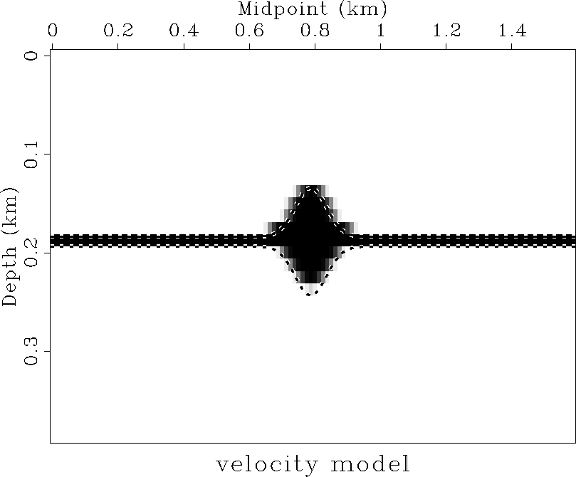 |
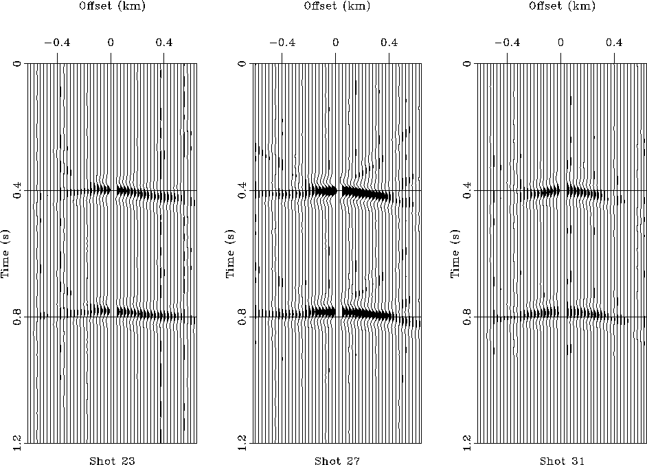 |
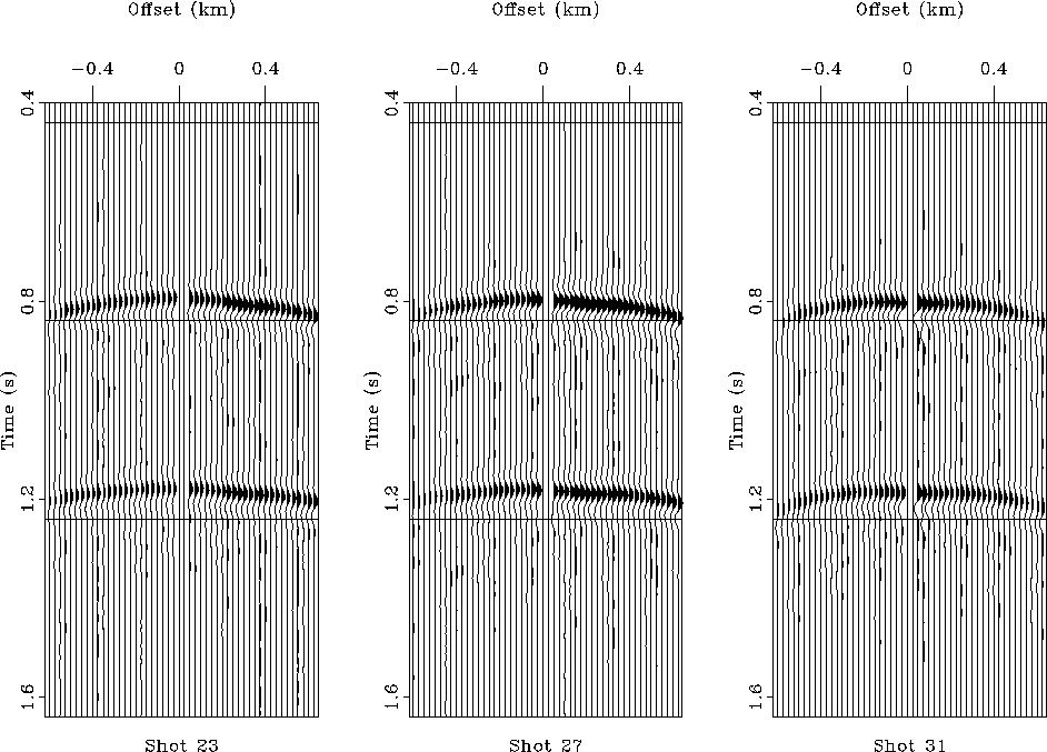
In Figure fdrep, the synthetics from Figure fddown have been upward continued with a constant replacement velocity. Most of the kinematic and some of the focusing distortions have been removed from the shot gathers (comparing Figure fdrep to Figure shot). The result is not perfect, but given the limited data aperture and the parameterization of the velocity model, it is encouraging.
 |
FUTURE WORK Although the preliminary version of the slant stack imaging code used in the synthetic data example produced an image of the anomaly, more work is required to refine the algorithm, eliminate artifacts, and increase resolution. The algorithm will be improved so that data are extended off-end in order to minimize truncation effects ().
The bulk of the remaining effort will concentrate on the development of the iterative wavefield inversion algorithm. One of the first questions to address is what are the best criteria for forming a suitable objective function? Some experimentation will be required to determine the best objective function in terms of stability, convergence, and efficiency.
The choice of extrapolation operator must also be determined. It might be worth evaluating Kirchhoff, finite-difference, and phase-shift extrapolation operators. Researching these methods would be beneficial because it may turn out that for long-term utility of the method, different extrapolations may be necessary for different applications. The Kirchhoff method is probably most suited for irregular acquisition geometries and for three-dimensional applications. The choice of extrapolation operator will determine how the velocity model will be parameterized and whether the derivatives used in the optimization method will be calculated numerically or analytically.
A gradient ascent method will be implemented to optimize the image of
the geological structure. Once an objective function Q is formed, a model
estimate ![]() will be used to form the gradient of the
objective function
will be used to form the gradient of the
objective function ![]() . The proposed gradient ascent
is illustrated by the following steps:
. The proposed gradient ascent
is illustrated by the following steps:
Once the objective function is clearly defined and the gradient stepping method is developed, the program will be tested for stability, convergence, and uniqueness. This testing will determine if the slant stack inversion results generated by the first step of NSVI are close enough to the problem's global minima for the optimization problem to be in a convex region and for it to converge rapidly.
Even if the estimated velocity model does not match the known model exactly, I will be able to determine if the solution is an acceptable one in terms of matching the original data. Since the final objective of the method proposed here is to image the geology below the near surface, a nonunique solution which matches the kinematics and amplitude effects of the near-surface sufficiently well to improve the deeper image is a desired and acceptable solution.
DISCUSSION AND CONCLUSIONS
There are several issues that must be addressed in order to determine the feasibility of the proposed NSVI method:
[SEP,GEOTLE,MISC,myrefs]
![[*]](http://sepwww.stanford.edu/latex2html/prev_gr.gif)