

![[*]](http://sepwww.stanford.edu/latex2html/prev_gr.gif)


ABSTRACTWe have developed a procedure for building a 3-D velocity model starting from a 2-D geological model in order to image 3-D poststack data. The 3-D model was built using GOCAD, and it was iteratively refined by interpreting the result of 3-D poststack depth migrations using AVS. At the beginning of the iterative process, when only few reflectors are detectable in the migrated cube, we interpret only one surface. From the deformations measured on the selected reflector we compute a displacement field for every point in the model. The application of the displacement field to the GOCAD model used for migration leads to an improved model. The migration of the data with this improved model shows better focusing of some reflectors and allows a more complete interpretation of the structure. |
INTRODUCTION
One of the most crucial problems in imaging 3-D seismic data is the determination of the velocity model. With the ever increasing speed of parallel supercomputers new options for defining and refining the velocity model are becoming possible. These new options take advantage of the speed of these super computers to integrate time consuming operations such as migration, into an interactive and iterative processing flow (, ). Sheppard and O'Brien took advantage of these new options by creating a 3-D velocity model by performing depth migration, interpreting the resulting image, and refining the geologic model. In addition, improved visualization software has made 3-D model building, viewing, and manipulating an easier task. Della Malva and Williams used GOCAD to combine a series of 2-D velocity models into a 3-D model. We blended elements of both of these methods in an attempt to obtain a good 3-D velocity model for 3-D poststack migration. We started with a 2-D geologic model, along with the prestack and poststack 3-D data sets in which initially very few reflectors were identifiable. We migrated the data with 2.5-D model created in GOCAD. We then viewed the 3-D cube using AVS and picked a series of surfaces on various slices of the cube parallel to the direction of the initial 2-D geologic model. From this series of surfaces we created a 2-D displacement net for the cube. Choosing a single surface and then extrapolating its changes in depth to the entire geologic model does not accurately describe geologic sedimentation and the time variant nature of the stress field accompanying it. The methodology is not a bad first approximation, and proved effective in improving the migrated image and the accompanying geologic model.
BUILDING THE 3-D GEOLOGIC MODEL
The first challenge was to convert the 2-D AIMS geologic model into a 3-D GOCAD model.
AIMS model
AIMS creates its model by constructing a series of surfaces defined by numerous line segments. These line segments are defined in an ASCII file by a pair of coordinates representing the beginning and end of the line segment. In addition to the coordinates, each line contains the number of the corresponding surface. The surfaces are chosen so that only one velocity is represented below them and that velocity is defined in a horizon call. An example of a portion of an AIMS 2-D model file is presented below:
3-D Model in GOCAD
As described in Berlioux a GOCAD 3-D model is defined by a series of surfaces files and a partition file. Each surface file is divided into two parts. The first part contains a series of points (vertices in the GOCAD nomenclature) upon which the surface lies. The second section is devoted to constructing a series of triangles from the defined points in order to give the surface continuity in two-dimensions. Figure gocad1 illustrates a simple model constructed from the surface file defined below: gocad1height=3inA simple GOCAD model.
The partition file defines a series of domains bounded by the various surfaces. The domains can then be assigned properties such as velocity or density.
The Conversion
Rather than converting the AIMS file manually into a series of GOCAD files it was decided to develop a procedure that would accomplish this task automatically. The conversion program was written in standard SEP-like format to better allow it to be integrated into future processing flows. The input is simply the AIMS file, parameters defining the extension in the cross-line direction, and an option to create a free surface. The output is a series of .ts files (GOCAD extension for a surface file) corresponding to the surfaces described by AIMS.
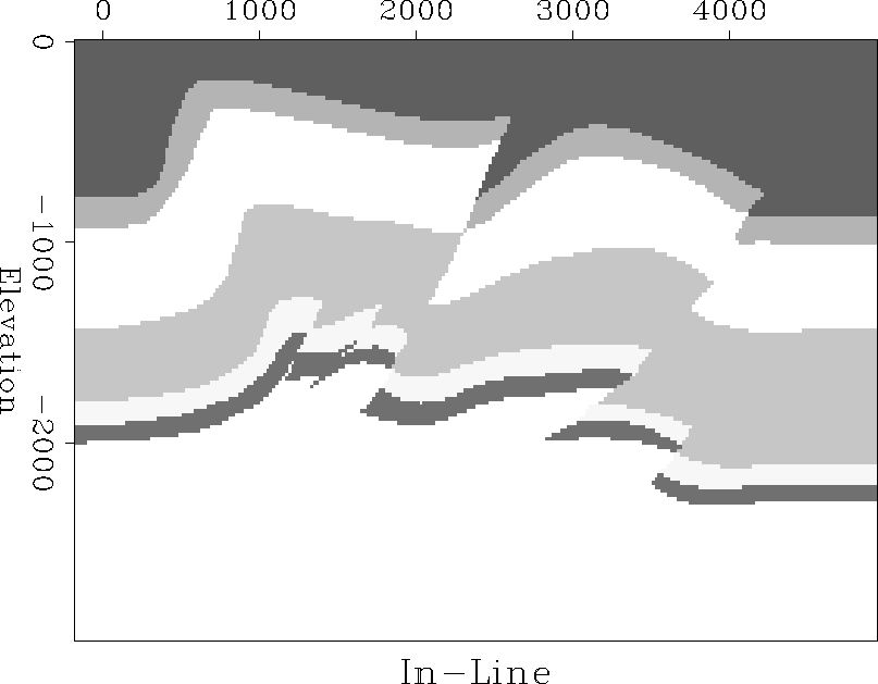
Once the initial AIMS file has been run through the conversion routine it is a relatively simple matter to create the GOCAD model. Figure gocad2 represents the GOCAD model corresponding to the input AIMS geologic model. gocad2width=7inGOCAD model corresponding to input AIMS model. In order to run the CM-5 migration program it is necessary to convert the GOCAD model to SEP format. Figure gocad3 represents a 2-D slice of the resulting velocity model using the program described in Berlioux.
 |
REFINING THE GEOLOGIC MODEL
Once the initial geologic model had been built, the task was to better describe the 3-D nature of the area. The velocity model was used as input to a depth migration program on the CM-5 developed at SEP (). The resulting cube was then viewed using AVS.
AVS picker
Dave Nichols has created an AVS network, and written a module for that network which enables the user to pick a polyline on a 2-D image and write that polyline in a GOCAD pline format. In order to create the displacement field, we chose a 2-D slice of the data cube parallel to the geologic model (see Figure avs3241), then chose a surface that was possible to identify on all/most of the 2-D images. We picked the surface on the image and saved it in a file corresponding to the slice number. Part of the recorded pline file for Figure avs3241 can be seen below: avs3241height=4inSlice 324 of 3-D migrated cube. We then attempted to pick the same pline on another in-line slice in order to approximately quantify the changes in depth along the cross-line direction of the geologic model. Figure avs220 shows a second slice in the in-line direction, note the change in the surface approximately 80% of the way down the image in comparison to the same surface on Figure avs3241. avs220height=4inSlice 220 of 3-D migrated cube.
Creating GOCAD model from series of plines Creating the 3-D GOCAD model from the series of 2-D plines was a two-step process. The first step was to create a 2-D displacement field. The displacement field was created by: first, reading in the series of vertices making up the various plines, then resampling in the in-line direction using linear interpolation between the points, and finally, subtracting the resampled values from a baseline corresponding to the original 2-D geologic model. The corresponding displacement net is specified by a user defined density parameter in the in-line direction and by the number of slices of the 3-D cube in which plines were chosen in the cross-line direction. It was not necessary to resample in the cross-line direction due to the combination of GOCAD and the gridding program doing the same linear interpolation as the program performs in the in-line direction. Once the 2-D displacement net has been created, Figure displacement1, the net is used to construct the same series, and in virtually the same manner, the .ts files constructed in the original 2.5-D GOCAD model.
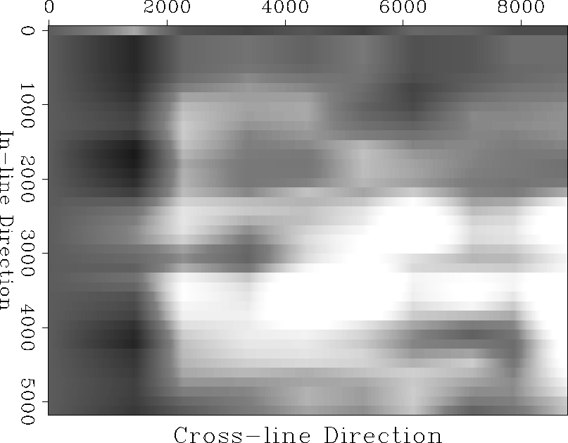 |
Figure gocad4 represents the GOCAD model derived from the displacement field shown in Figure displacement1. gocad4width=7inGOCAD model constructed from initial displacement field calculations.
Even though the initial data quality was poor, and the re-migrated image far fro m ideal (Figure avs3242), the image does appear to be improved compared to the corresponding slice migrated with the initial 2.5-D velocity model, Figure avs3241. The improvement is especially noticeable in the middle of the image where an anticline has become better focused. avs3242height=4inSlice 324 of migrated cube with 3-D velocity model.
CONCLUSIONS
By creating a 2-D displacement net and applying it to the geologic model, the 3-D poststack migration image did show some improvement. The velocity model could be further improved by re-choosing the surface on the series of 2-D slices. The improved quality of the velocity function should enable a more consistent and improved picking, further enhancing the quality of the 3-D model. Further, once the surfaces become more apparent in the migrated image, extending the displacement field into the third dimension by picking two or more surfaces might help improve the results and better approximate the true nature of sedimentation variation with time. In addition velocity inside the model could be better defined by intergrating geophysical data derived from such source as velocity analysis.
ACKNOWLEDGEMENTS
We would like to thank Husky Oil for providing the dataset, and in particular Fred Kierulf with Husky Oil, for his enthusiastic support. At SEP, we are indebted with Arnaud Berlioux for the numerous hours spent explaining GOCAD and his gridding program, and Dave Nichols for explaining some of the intricacies of AVS and his network. [SEP,bib1]