


Next: POSTSTACK GAUSSIAN BEAM DEPTH
Up: Mo: Gaussian beam
Previous: Introduction
Gaussian beam wavefield computation is based on the simulation of
the wavefield by a system of Gaussian beams by an asymptotic procedure.
Since V. Cerveny and his colleagues are largely responsible
for the early development of Gaussian beam seismic wave propagation theory,
this quotation from their classic paper (Cerveny et al. 1982)
is the best introduction to the subject:
The wave field generated by a line source
in a 2-D laterally inhomogeneous medium is decomposed into contributions,
corresponding to individual rays. These contributions are evaluated along
the rays by the parabolic wave equation method. The parabolic wave equation
method gives solutions of the wave equation concentrated close to rays. From
the physical point of view these solutions correspond to the Gaussian beams.
Each beam is continued independently through an
arbitrary inhomogeneous structure.
The complete wave field at a receiver is then obtained as an
integral superposition of all Gaussian beams arriving in some neighbourhood
of the receiver. The corresponding integral formula is valid even in
various singular regions where the ray method fails (the vicinity of caustic,
critical point, etc.).
The Gaussian beam approach to the problem of wave propagation
is to obtain a local paraxial solution to the exact wave equation.
The exact monochromatic wave equation is the Helmholtz equation
| 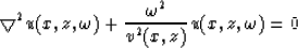 |
(1) |
where  is the angular frequency and v(x,z) is the wave velocity at
the point (x,z).
Gaussian beam wavefield computation uses high frequency
asymptotic approximation to transform the Helmholtz equation into a parabolic
wave equation in ray-centered coordinates (s,n)
(Cerveny et al., 1982, equation (11)), as follows:
is the angular frequency and v(x,z) is the wave velocity at
the point (x,z).
Gaussian beam wavefield computation uses high frequency
asymptotic approximation to transform the Helmholtz equation into a parabolic
wave equation in ray-centered coordinates (s,n)
(Cerveny et al., 1982, equation (11)), as follows:
| 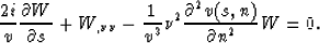 |
(2) |
The relation between u and W is expressed by the equation
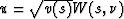 .
Variables s and n are the ray centered coordinates,
and
.
Variables s and n are the ray centered coordinates,
and  . The coordinate s
measures the arclength along the ray from an arbitrary reference point, and n
represents a length coordinate in the direction perpendicular to the ray
at s.
The solutions of this parabolic wave equation are evaluated along rays by
dynamic ray tracing. And the solutions are called Gaussian beams.
. The coordinate s
measures the arclength along the ray from an arbitrary reference point, and n
represents a length coordinate in the direction perpendicular to the ray
at s.
The solutions of this parabolic wave equation are evaluated along rays by
dynamic ray tracing. And the solutions are called Gaussian beams.
The details of Gaussian beam computation have been given by previous authors
(Cerveny et al., 1982; Cerveny, 1983; Cerveny and Psencik, 1984;
Nowack and Aki, 1984).
Here I summarize them into five steps. Steps (I) and (II)
are ray tracing. Steps (III), (IV) and (V)
are the computation of wavefields by the Gaussian beam approach.
(I) Conventional kinematic ray tracing - From each surface point source
location, a few rays are traced by the standard raypath equations
(Cerveny et al., 1977)
|  |
(3) |
|  |
(4) |
|  |
(5) |
Variable v(x,z) is the wave propagation velocity,  is the traveltime
along the ray, x and z are the horizontal and vertical Cartesian
coordinates along the ray, and
is the traveltime
along the ray, x and z are the horizontal and vertical Cartesian
coordinates along the ray, and  is the angle between the tangent of
the ray at the location (x,z) and the positive z axis.
This system of ODEs can be integrated by a standard numerical method,
such as the fourth-order Runge-Kutta method.
This form of the ray tracing system of equations
is very convenient for computation; the traveltime along the ray is just the
product of the integration index step and the integration step size
is the angle between the tangent of
the ray at the location (x,z) and the positive z axis.
This system of ODEs can be integrated by a standard numerical method,
such as the fourth-order Runge-Kutta method.
This form of the ray tracing system of equations
is very convenient for computation; the traveltime along the ray is just the
product of the integration index step and the integration step size  ,
and the ray centered coordinates (s,n) of the depth image points
relative to the ray path can be easily computed.
At an interface, Snell's law is applied locally.
,
and the ray centered coordinates (s,n) of the depth image points
relative to the ray path can be easily computed.
At an interface, Snell's law is applied locally.
(II) Dynamic ray tracing - Simultaneously with step (I)
we integrate the dynamic ray tracing system of ODEs
| 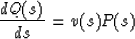 |
(6) |
and
| 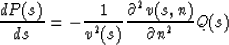 |
(7) |
The scalar functions P(s) and Q(s) are complex.
These functions determine the Gaussian beam parabolic wavefront curvature
and the Gaussian function amplitude profile.
This system of ODEs can be transferred to the Cartesian coordinate system
for computation, as follows:
|  |
(8) |
and
|  |
(9) |
where
|  |
(10) |
(III) Solution of the parabolic wave equation by the Gaussian beam method
- Next we calculate the wavefield  associated with
the raypath by evaluating the function
associated with
the raypath by evaluating the function
| ![\begin{displaymath}
u(s,n,\omega) = {\left[ v(s) \over Q(s) \right]}^{1/2} exp \...
...au (s) + {i\omega\over 2} {P(s)\over Q(s)} n^2 \right] \right\}\end{displaymath}](img19.gif) |
(11) |
This is the Gaussian beam. It is an asymptotic local paraxial solution
of the complete monochromatic Helmholtz wave equation
concentrated close to the ray path.
The variable signum determines whether the propagation phase increases or
decreases, and it is assigned the value +1 or -1 depending on whether it
is in migration or modeling and on the sign convention of the Fourier transform.
The second term in the exponential determines that
the wavefront is a parabola and that
the amplitude profile is a Gaussian function, hence the name Gaussian beam.
The higher the frequency is, the sharper the parabolic wavefront and
the narrower the Gaussian amplitude profile.
As the ray path is usually curved, Gaussian beam wavefields are evaluated
only at a region along the ray at which the ray-centered coordinate system
(s,n) is regular called ``the regularity region,'' that is, a region at
certain distances from the ray before the system of normals constructed to
the ray path intersect.
Gaussian beam solution (11) is well-behaved if
and
|  |
(13) |
for all ray path length s.
Cerveny et al. (1982) show that it is possible to choose the
initial values of P(s) and Q(s) such that inequalities (12) and (13)
are always true. And there is latitude in the choice of the initial values
P0=P(s=0) and Q0=Q(s=0). This choice
determines the initial width and wavefront curvature of the Gaussian beams.
Hill (1990) conveniently designated the initial values of
P0 and Q0 to be
|  |
(14) |
and
|  |
(15) |
Parameter  specifies the initial beam width
at some reference angular frequency
specifies the initial beam width
at some reference angular frequency  .
And is chosen to be
at the lower end of the seismic data spectrum. Va is a global
spatial average of the velocities occurring in the background velocity model,
and V0 is the velocity at the source point s=n=0.
.
And is chosen to be
at the lower end of the seismic data spectrum. Va is a global
spatial average of the velocities occurring in the background velocity model,
and V0 is the velocity at the source point s=n=0.
(IV) Expansion of the wavefields into Gaussian beams -
The point source wavefields can be expanded into a series of solutions
concentrated close to the rays, the Gaussian beams, as
| 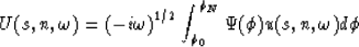 |
(16) |
The function  is a weighting factor for decomposing a point source
wavefield into Gaussian beams, and its value
depends on the takeoff angle
is a weighting factor for decomposing a point source
wavefield into Gaussian beams, and its value
depends on the takeoff angle  of the ray. And the angle is measured from the vertical direction.
I implement it as
of the ray. And the angle is measured from the vertical direction.
I implement it as  as in Kirchhoff migration.
(V) Construction of the wavefields in the time domain -
If we let the spectrum of the source time function be  , then by
Fourier transform, we can construct the time domain wavefields as
, then by
Fourier transform, we can construct the time domain wavefields as
| 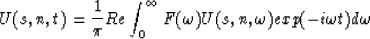 |
(17) |
Next: POSTSTACK GAUSSIAN BEAM DEPTH
Up: Mo: Gaussian beam
Previous: Introduction
Stanford Exploration Project
11/17/1997