

Next: The zero-offset waveform
Up: DYNAMIC BEHAVIOR
Previous: DYNAMIC BEHAVIOR
Figure ![[*]](http://sepwww.stanford.edu/latex2html/cross_ref_motif.gif) describes the model parameters.
Figure
describes the model parameters.
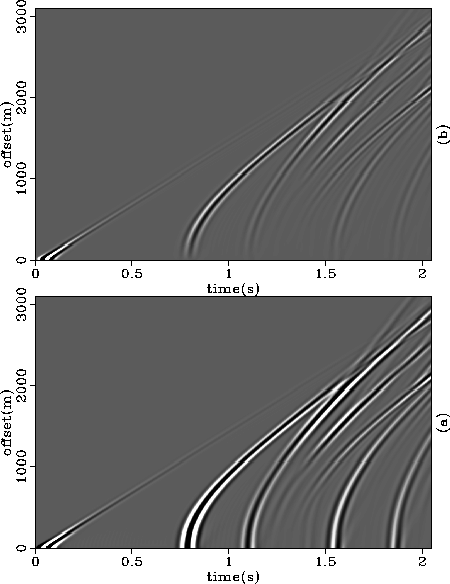
Figure ![[*]](http://sepwww.stanford.edu/latex2html/cross_ref_motif.gif) shows the horizontal and vertical components of
the wavefield generated by the dual-operator modeling scheme
using the model of Figure
shows the horizontal and vertical components of
the wavefield generated by the dual-operator modeling scheme
using the model of Figure ![[*]](http://sepwww.stanford.edu/latex2html/cross_ref_motif.gif) . The reflections with zero-offset
traveltime equal to 0.8, 1.1, and 1.55 seconds correspond, respectively, to
the water-bottom reflection, the reflection in the interface between
the second and third layers, and the first multiple of the water-bottom
reflection. The two other visible reflections correspond to the PS and
SS reflections at the interface between the second and third layers.
Mod.model
. The reflections with zero-offset
traveltime equal to 0.8, 1.1, and 1.55 seconds correspond, respectively, to
the water-bottom reflection, the reflection in the interface between
the second and third layers, and the first multiple of the water-bottom
reflection. The two other visible reflections correspond to the PS and
SS reflections at the interface between the second and third layers.
Mod.model
Figure 1 Model used to compare the results obtained with three different
modeling schemes. Elastic constants are given in  ,
and densities in
  .
.

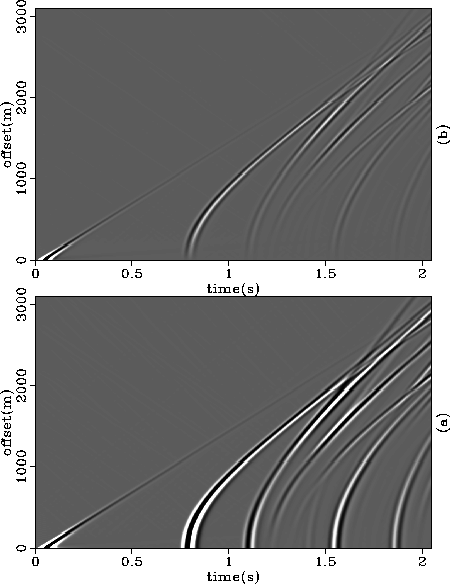
Figure ![[*]](http://sepwww.stanford.edu/latex2html/cross_ref_motif.gif) shows the vertical and horizontal components of
the wavefield generated with the Haskell-Thomson scheme, and
Figure
shows the vertical and horizontal components of
the wavefield generated with the Haskell-Thomson scheme, and
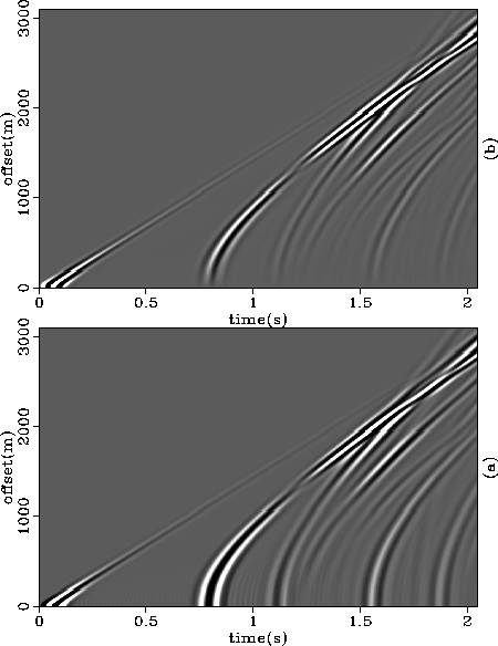
Figure ![[*]](http://sepwww.stanford.edu/latex2html/cross_ref_motif.gif) shows the vertical and horizontal components
of the wavefield generated with the traditional finite-difference scheme.
shows the vertical and horizontal components
of the wavefield generated with the traditional finite-difference scheme.
avoti
Figure 2 Surface wavefield generated by the dual-operator scheme.
(a) Vertical component. (b) Horizontal component.


 avosld
Figure 3 Surface wavefield generated by the propagator-matrix scheme.
(a) Vertical component. (b) Horizontal component.


 avoelas
Figure 4 Surface wavefield generated by the traditional finite-difference scheme.
(a) Vertical component. (b) Horizontal component.


The wavelet is clearly broader in both finite-difference-based methods
because they require that the source extends over more than one grid-point.
That is also the reason for the small precursor lobe in the wavelet generated
by these two methods. Although both finite-difference schemes have operators
with the same number of points (of same order in time and space), the
traditional method is more dispersive, as indicated by the high-frequency
ringing that contaminates the near traces of the vertical component.
This higher dispersion is noticeable mainly when a liquid layer is present.
Other differences are: the phase change of the sea bottom reflection
near the offset 1300 meters in the vertical component of the traditional
finite-difference scheme, the much weaker amplitude of the PSSP mode (the third
event from the bottom) in the traditional finite-difference scheme,
and the weaker near-offset amplitude of the PSPP mode (the fourth event from
the bottom) in both finite-difference schemes relative to the
propagator-matrix scheme.


Next: The zero-offset waveform
Up: DYNAMIC BEHAVIOR
Previous: DYNAMIC BEHAVIOR
Stanford Exploration Project
11/18/1997

![[*]](http://sepwww.stanford.edu/latex2html/cross_ref_motif.gif) describes the model parameters.
Figure
describes the model parameters.
Figure ![[*]](http://sepwww.stanford.edu/latex2html/cross_ref_motif.gif) shows the horizontal and vertical components of
the wavefield generated by the dual-operator modeling scheme
using the model of Figure
shows the horizontal and vertical components of
the wavefield generated by the dual-operator modeling scheme
using the model of Figure ![[*]](http://sepwww.stanford.edu/latex2html/cross_ref_motif.gif) . The reflections with zero-offset
traveltime equal to 0.8, 1.1, and 1.55 seconds correspond, respectively, to
the water-bottom reflection, the reflection in the interface between
the second and third layers, and the first multiple of the water-bottom
reflection. The two other visible reflections correspond to the PS and
SS reflections at the interface between the second and third layers.
. The reflections with zero-offset
traveltime equal to 0.8, 1.1, and 1.55 seconds correspond, respectively, to
the water-bottom reflection, the reflection in the interface between
the second and third layers, and the first multiple of the water-bottom
reflection. The two other visible reflections correspond to the PS and
SS reflections at the interface between the second and third layers.

![[*]](http://sepwww.stanford.edu/latex2html/cross_ref_motif.gif) shows the vertical and horizontal components of
the wavefield generated with the Haskell-Thomson scheme, and
Figure
shows the vertical and horizontal components of
the wavefield generated with the Haskell-Thomson scheme, and
Figure ![[*]](http://sepwww.stanford.edu/latex2html/cross_ref_motif.gif) shows the vertical and horizontal components
of the wavefield generated with the traditional finite-difference scheme.
shows the vertical and horizontal components
of the wavefield generated with the traditional finite-difference scheme.


