|
|
|
|
Fast 3D velocity updates using the pre-stack exploding reflector model |
Despite the recent good migration results obtained in geologically complex areas using wide-azimuth data, narrow-azimuth acquisition is still the industry standard. Narrow-azimuth data can be efficiently imaged by common-azimuth wave-equation migration (CAM) (Biondi and Palacharla, 1996). By assuming zero cross-line offset in contrast with the full-azimuth migration, instead of a five-dimensional hypercube, CAM images are four-dimensional hypercubes in ![]() and
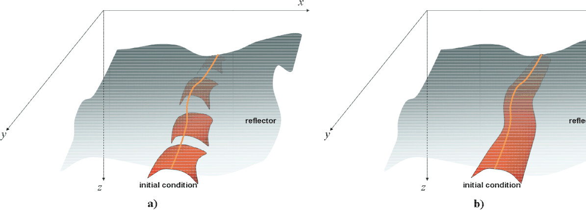
and ![]() . Because of the lower dimensionality of CAM images, when using them as the initial conditions to synthesize PERM data, the SODCIGs in the cross-line direction can be sampled continuously, as depicted in Figure 1b. Contrast this case with the five-dimensional initial conditions for the full azimuth case of Figure 1a. The continuous sampling of SODCIGs in the cross-line direction yields one more order of magnitude of data reduction. Therefore, under the common-azimuth assumption, 3D-PERM data size can be two orders of magnitude smaller than 3D-plane wave data.
. Because of the lower dimensionality of CAM images, when using them as the initial conditions to synthesize PERM data, the SODCIGs in the cross-line direction can be sampled continuously, as depicted in Figure 1b. Contrast this case with the five-dimensional initial conditions for the full azimuth case of Figure 1a. The continuous sampling of SODCIGs in the cross-line direction yields one more order of magnitude of data reduction. Therefore, under the common-azimuth assumption, 3D-PERM data size can be two orders of magnitude smaller than 3D-plane wave data.

|
|---|
|
cam01
Figure 1. The initial conditions for synthesizing PERM data from CAM images can be specified as in b) because no pre-stack information exists in the cross-line direction, in contrast with the full azimuth situation in a). |
|
|
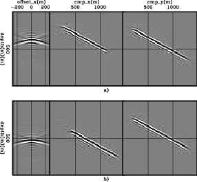
To illustrate the validity of the above assumptions, a split-spread data with maximum offset of 1587.5 m was computed using 3D-Born modeling on a 30![]() dipping reflector with 45
dipping reflector with 45![]() azimuth with respect to the acquisition direction. There are 96 in-lines and cross-lines spaced 25 m apart. The offset interval is 25 m. The velocity used in the modeling is the 1D function
azimuth with respect to the acquisition direction. There are 96 in-lines and cross-lines spaced 25 m apart. The offset interval is 25 m. The velocity used in the modeling is the 1D function
![]() m/s. The Born data are input to CAM with a 5
m/s. The Born data are input to CAM with a 5![]() slower velocity. Migration results can be seen in Figures 2a and 2b for SODCIGs positioned at
slower velocity. Migration results can be seen in Figures 2a and 2b for SODCIGs positioned at ![]() m,
m, ![]() m
m![]() and
and ![]() m,
m, ![]() m
m![]() , respectively. The panel on the left is the SODCIG, which contains 21 subsurface offsets ranging from
, respectively. The panel on the left is the SODCIG, which contains 21 subsurface offsets ranging from ![]() m to
m to ![]() m. The panel in the middle is the in-line at zero subsurface offset, with
m. The panel in the middle is the in-line at zero subsurface offset, with ![]() m (Figure 2a) and
m (Figure 2a) and ![]() m (Figure 2b). The panel on the right is the cross-line at zero subsurface offset, with
m (Figure 2b). The panel on the right is the cross-line at zero subsurface offset, with ![]() m.
m.
In the common-azimuth regime, the computation of the dip-independent initial conditions is performed by simply rotating the SODCIGs in the in-line direction, since no cross-line offset is computed in migration.
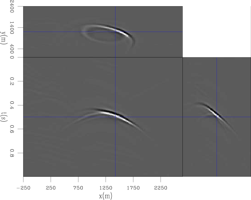
PERM source and receiver wavefields were modeled using as the initial conditions combined SODCIGs from the CAM image (Figure 2) with continuous sampling along the cross-line direction and sampling period of 48 in the in-line direction. This period is sufficient to avoid crosstalk during the areal-shot migration, given that the number of subsurface-offsets of the pre-stack image is 21. One synthesized 3D receiver wavefield is shown in Figure 3. The left panel is the in-line at ![]() m, the right panel is the cross-line at
m, the right panel is the cross-line at ![]() m, and the top panel is the time-slice at
m, and the top panel is the time-slice at ![]() s.
s.
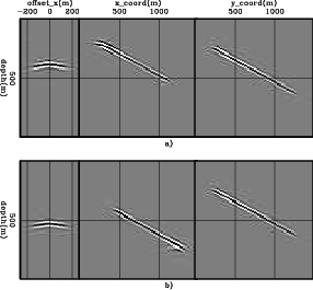
The 3D migration of the 48 areal shots with the velocity underestimated by 5![]() is shown in Figures 4a and 4b for SODCIGs positioned at
is shown in Figures 4a and 4b for SODCIGs positioned at ![]() m,
m, ![]() m
m![]() and
and ![]() m,
m, ![]() m
m![]() , respectively. The kinematics of the SODCIGs computed with PERM wavefields matches those of the SODCIGs computed with CAM. This enables the use of 3D PERM wavefields computed from CAM images in optimization of migration velocity, as will be shown next for a 3D survey from the North Sea.
, respectively. The kinematics of the SODCIGs computed with PERM wavefields matches those of the SODCIGs computed with CAM. This enables the use of 3D PERM wavefields computed from CAM images in optimization of migration velocity, as will be shown next for a 3D survey from the North Sea.

|
|---|
|
cam02
Figure 2. CAM of the 3D-Born data. Middle: in-line at zero-subsurface offset, and |
|
|

|
|---|
|
cam03
Figure 3. 3D-PERM receiver wavefield. The left panel is the in-line at |
|
|

|
|---|
|
cam04
Figure 4. 3D-areal-shot migration of PERM data. Middle: in-line at zero-subsurface offset, and |
|
|
|
|
|
|
Fast 3D velocity updates using the pre-stack exploding reflector model |